
Calcium carbide sensible heat recovery equipment and method for calcium carbide furnace

A sensible heat recovery, calcium carbide furnace technology, applied in lighting and heating equipment, furnaces, waste heat treatment and other directions, can solve problems such as large energy consumption, environmental pollution, smoke and dust release, etc., to improve economic benefits, improve the environment, and reduce pollution. Effect

Inactive Publication Date: 2014-05-07
XIAN UNIV OF SCI & TECH
View PDF11 Cites 17 Cited by
  • Summary
  • Abstract
  • Description
  • Claims
  • Application Information

AI Technical Summary

Problems solved by technology

In the transformation of large-scale power-consuming equipment, energy saving and consumption reduction, smoke and dust removal, especially large submerged arc furnaces, consume a lot of energy. In the production of calcium carbide, not only a large amount of smoke and dust are released into the air to pollute the environment, but also take away a large amount of Heat is lost to the surrounding environment causing waste
Aiming at the above problems, the elimination of smoke and dust and the energy taken away in the production of calcium carbide has achieved certain results, but the work of recovering the energy emitted by calcium carbide when it is released from the furnace has not yet been developed in China, and it is a blank

Method used


Image

  • Calcium carbide sensible heat recovery equipment and method for calcium carbide furnace

Examples


Embodiment Construction

[0045] The present invention will be further described below in conjunction with the drawings and embodiments.

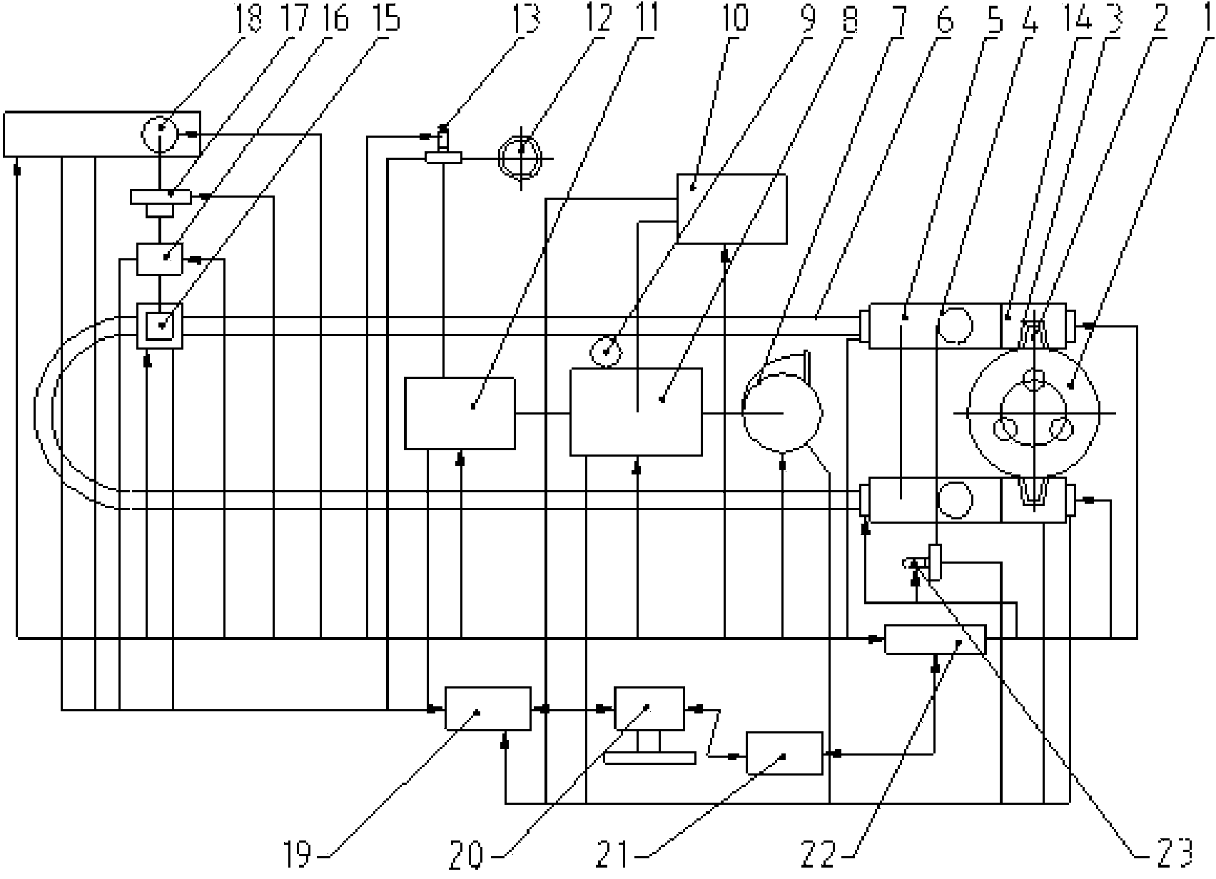
[0046] Reference figure 1 As shown, a calcium carbide furnace calcium carbide sensible heat recovery equipment of the present invention includes a calcium carbide furnace 1 and a calcium carbide flow tank 2 arranged on the calcium carbide furnace 1. The lower part of the calcium carbide furnace 1 is erected on a circular track 6 through a calcium carbide furnace cart 4, and the calcium carbide furnace The upper part of the furnace 1 is connected with the blower 23. The calcium carbide furnace 1 is respectively connected to the hot air tunnel kiln 5 through the calcium carbide flow trough 2 and the smoke hood 3, and is connected to the high temperature cyclone dust collector 7 through the furnace top smoke pipe, the high temperature cyclone dust collector 7 and the waste heat The boiler 8 is connected, and the waste heat boiler 8 is respectively connected to the user 10...


PUM


Abstract

The invention discloses calcium carbide sensible heat recovery equipment and method for a calcium carbide furnace. The equipment comprises a calcium carbide furnace and a calcium carbide chute arranged on the calcium carbide furnace, wherein the lower part of the calcium carbide furnace is erected on an annular track through a calcium carbide furnace trolley; the upper part of the calcium carbide furnace is connected with an air blower, and the calcium carbide furnace is communicated with a hot air tunnel kiln through the calcium carbide chute and a smoke exhaust hood; a furnace top smoke pipeline is communicated with a high-temperature cyclone dust collector which is communicated with a waste heat boiler, and the waste heat boiler is communicated with a user and a bag type dust collector respectively; the calcium carbide furnace erected on the annular track is connected to a jaw crusher through an upending device, connects a bucket elevator to a storage hopper through the jaw crusher, then is connected to a chain scraper conveyor through an articulated chute, and is connected to a storehouse through the chain scraper conveyor; and the equipment further comprises a PLC (programmable logic controller) console which is connected to the storehouse through an industrial machine. With the adoption of the calcium carbide sensible heat recovery equipment for the calcium carbide furnace, a large amount of dissipated heat in calcium carbide production is utilized reasonably, effectively and sufficiently, the comprehensive effects of energy saving, consumption and pollution reduction, environment improvement and cost reduction are achieved, and the economic benefit is increased.

Description

Technical field [0001] The invention relates to a device for utilizing heat energy in the production of calcium carbide, in particular to a device for recovering the sensible heat of calcium carbide produced by a calcium carbide furnace. Background technique [0002] The calcium carbide industry was born in the last century. At that time, the capacity of calcium carbide furnaces was small, generally less than 300KVA. The production of furnaces was very backward. Single-phase power supply and intermittent operation were usually used. The labor intensity was very heavy. Later, it developed into automatic sintering electrodes and semi-closed electric furnaces. With the vigorous development of the organic synthesis industry, the calcium carbide industry has become more prosperous, and the equipment for producing calcium carbide has gradually replaced open or semi-closed calcium carbide furnaces with closed calcium carbide furnaces. Nevertheless, this kind of enclosed calcium carbide ...

Claims


Application Information

Patent Timeline
IPC IPC(8): F27D17/00
CPCY02P10/25
Inventor 王昀睿
Owner XIAN UNIV OF SCI & TECH
Learn More