Method for determining open cup flash point of oil product

A technology for open flash point and oil products, which is applied in the field of determination of open flash point of oil products, can solve the problems of poor precision of measurement results, harmfulness to human body, strict environmental requirements, etc., and achieves small deviation, good correlation and good precision Effect

Active Publication Date: 2014-05-07
CHINA PETROLEUM & CHEM CORP +1
View PDF0 Cites 2 Cited by
  • Summary
  • Abstract
  • Description
  • Claims
  • Application Information

AI Technical Summary

Problems solved by technology

These two conventional analysis methods have the following disadvantages: (1) During the analysis process, the sample is heated to produce harmful steam; (2) The amount of sample used for the measurement is large, about 200mL sample is required; (3) The measurement results The precision is poor, such as the deviation of the measurement result is 8-16°C; (4) This method has strict requirements on t

Method used


Image

  • Method for determining open cup flash point of oil product
  • Method for determining open cup flash point of oil product
  • Method for determining open cup flash point of oil product

Examples


Embodiment 1

[0033] This embodiment is used to illustrate the method for measuring the open flash point of oil products of the present invention.

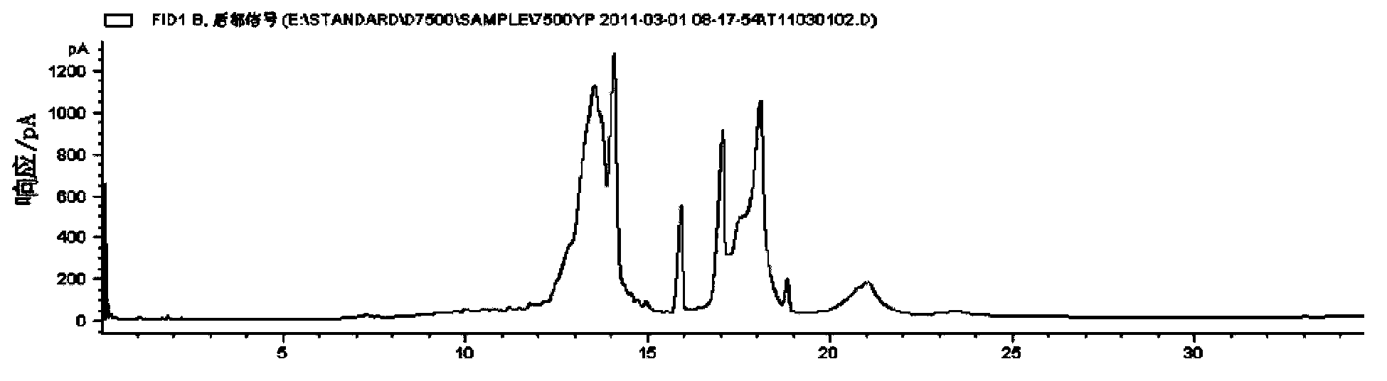
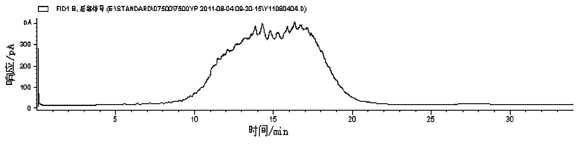
[0034] According to the method of NB / SH / T0829-2010 "Determination of Boiling Range Distribution of Petroleum Fractions with Boiling Range 174℃~700℃ (Gas Chromatography)", the boiling range distribution of internal combustion engine oils of the same brand but with different base oil compositions was measured. its T 10% , and substitute the test results into the correlation formula (1) for calculation to obtain its open flash point; and calculate the open flash point (measured value) measured according to the method of GB / T3536-2008 The difference of the open flash point (calculated value), the results are shown in Table 1 below.

[0035] Table 1

[0036]

Embodiment 2

[0038] This embodiment is used to illustrate the method for measuring the open flash point of oil products of the present invention.

[0039] According to the method of NB / SH / T 0829-2010 "Determination of Boiling Range Distribution of Petroleum Fractions with a Boiling Range of 174°C to 700°C (Gas Chromatography)", the boiling range distribution of internal combustion engine oils of the same brand but with different base oil compositions was measured. Get it 3% and T 10% , and substitute the test results into the correlation formula (2) for calculation to obtain its open flash point; at the same time, according to the method of GB / T 3536-2008, the open flash point of each internal combustion engine oil sample was tested respectively, and calculated according to GB / T 3536 The difference between the open flash point (measured value) measured by the method of -2008 and the open flash point (calculated value) calculated by formula (1), the results are shown in Table 2 below.

[...

Embodiment 3

[0043] This embodiment is used to illustrate the method for measuring the open flash point of oil products of the present invention.

[0044] According to the method of NB / SH / T 0829-2010 "Determination of Boiling Range Distribution of Petroleum Fractions with Boiling Range 174℃~700℃ (Gas Chromatography)", the boiling range distribution of different brands of internal combustion engine oil was measured, and the T 3% and T 10% , and substituting the test results into the correlation formulas (1) and (2) for calculation to obtain the open flash point; and calculate the open flash point (measured value) and The difference between the open flash point (calculated value 1) calculated according to the correlation formula (1) and the open flash point (calculated value 2) calculated according to the correlation formula (2), the results are shown in Table 3 below.

[0045] table 3

[0046]


PUM


Abstract

The invention relates to a method for determining open cup flash point of oil product, which comprises the following steps: determining boiling range distribution of oil product by using a gas chromatography method, and calculating the open cup flash point of the oil product according to the obtained boiling range distribution result by using a correlation formula. According to the invention, the method for determining open cup flash point of oil product can accurately determine open cup flash point of oil product with small deviation of detection result.

Description

technical field [0001] The invention relates to a method for measuring the open flash point of oil products. Background technique [0002] At present, there are two standard methods for determining the open flash point of oil products at home and abroad, namely: ASTM D92 "Determination of Flash Point and Ignition Point (Cleveland Open Cup Method)" and GB / T 3536 "Determination of Flash Point and Ignition Point of Petroleum Products ( Cleveland Open Cup Method). These two conventional analysis methods have the following disadvantages: (1) During the analysis process, the sample is heated to produce harmful steam; (2) The amount of sample used for the measurement is large, about 200mL sample is required; (3) The measurement results The precision is poor, such as the deviation of the measurement result is 8-16°C; (4) This method has strict requirements on the environment, such as: the measurement device is required to be placed in a sheltered and dark place, and surrounded by a...

Claims


Application Information

Patent Timeline
IPC IPC(8): G01N25/52
Inventor 金珂
Owner CHINA PETROLEUM & CHEM CORP
Why Eureka
Try Eureka