
Angle estimation method of bistatic MIMO (Multiple-Input Multiple-Output) radar high-speed and high-maneuvering target

A high maneuvering target and angle estimation technology, which is applied to radio wave measurement systems, instruments, etc., can solve the problems of sacrificing the channel separation performance of matched filters and the inability to achieve optimal performance of virtual arrays, etc., which is beneficial to engineering implementation and has low computational load , the effect of improving the estimation accuracy

Inactive Publication Date: 2014-05-07
南京拉伯王环保科技有限公司
View PDF3 Cites 19 Cited by
  • Summary
  • Abstract
  • Description
  • Claims
  • Application Information

AI Technical Summary

Problems solved by technology

In order to avoid the matched filter mismatch, this method expands its Doppler tolerance by reducing the matched filter duration, but sacrifices the channel separation performance of the matched filter, so that the performance of the virtual array formed by the MIMO radar cannot be optimal

Method used


Image

  • Angle estimation method of bistatic MIMO (Multiple-Input Multiple-Output) radar high-speed and high-maneuvering target
  • Angle estimation method of bistatic MIMO (Multiple-Input Multiple-Output) radar high-speed and high-maneuvering target
  • Angle estimation method of bistatic MIMO (Multiple-Input Multiple-Output) radar high-speed and high-maneuvering target

Examples


Embodiment Construction

[0023] The present invention will be further explained below in conjunction with the accompanying drawings and specific embodiments. It should be understood that the following specific embodiments are only used to illustrate the present invention and are not intended to limit the scope of the present invention. It should be noted that the words "front", "rear", "left", "right", "upper" and "lower" used in the following description refer to the directions in the drawings, and the words "inner" and "outer ” refer to directions towards or away from the geometric center of a particular part, respectively.

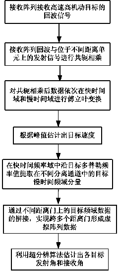
[0024] A method for estimating the angle of a bistatic MIMO radar high-speed and high-mobility target of the present invention comprises the following steps:

[0025] Step 1: Receive the echo signal of the high-speed and high-maneuvering target through the receiving array of the bistatic MIMO radar.

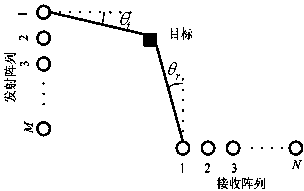
[0026] Assume that the bistatic MIMO radar transmit array and receive array ...


PUM


Abstract

The invention discloses an angle estimation method of a bistatic MIMO (Multiple-Input Multiple-Output) radar high-speed and high-maneuvering target. The angle estimation method comprises the steps of receiving an echo signal of a high-speed and high-maneuvering target by a receiving array of a bistatic MIMO (Multiple-Input Multiple-Output) radar; performing conjugate multiplication on echo of the receiving array and sending signals in different distant units; performing Fourier transform on data after performing conjugate multiplication in a fast time domain and a slow time domain in sequence; estimating a target speed according to a peak value in the step 3; extracting target slow time frequency domain components of different separation channels in a fast time frequency domain along with a target Doppler frequency value; splicing target frequency domain data in different distance gates to form virtual array data crossing a plurality of distance gates; and estimating sending angles and receiving angles of the targets by using a super-resolution algorithm. Through the angle estimation method, the influence on separation of MIMO radar channels caused due to high-speed and high-maneuvering movement of the target can be avoided; an effective virtual array can be formed by crossing the plurality of distance gates; and the problem of target angle parameter estimation of the bistatic MIMO radar under the high-speed and high-maneuvering target can be solved.

Description

technical field [0001] The invention relates to the application field of a multi-input multi-output radar system, in particular to a method for estimating the angle of a high-speed and high-mobility target of a bistatic MIMO radar. Background technique [0002] The bistatic radar with separate transceivers has strong anti-anti-radiation missiles, anti-electronic jamming, anti-low-altitude penetration and anti-stealth "four anti-" capabilities, while multiple-input multiple-output (Multiple-Input Multiple-Output, MIMO) The technology is applied to the bistatic radar, which can solve the problem of the synchronization of the sending and receiving space beams in the traditional bistatic radar. Therefore, bistatic MIMO radar has a broad application prospect, and its target detection and parameter estimation have become a research hotspot in the field of radar. The transmitting array of the bistatic MIMO radar transmits mutually orthogonal signals, and the receiving array far aw...

Claims


Application Information

Patent Timeline
IPC IPC(8): G01S7/41
CPCG01S7/41
Inventor 陈金立李家强朱艳萍于兵顾红
Owner 南京拉伯王环保科技有限公司
Learn More