plasma source

A plasma source, plasma technology, applied in the direction of plasma, ion beam tube, cathode ray tube/electron beam tube, etc., can solve the problems of need to replace immediately, the thickness of the prevention plate is thin, avoid collision, improve operation rate, the effect of prolonging the exchange period

Inactive Publication Date: 2015-11-11
NISSIN ION EQUIP CO LTD
View PDF8 Cites 0 Cited by
  • Summary
  • Abstract
  • Description
  • Claims
  • Application Information

AI Technical Summary

Problems solved by technology

However, if the anti-slip plate is not thick enough, although the collision between the electrons and the anti-slip plate can be avoided, because the anti-slip plate is thin, there is a corresponding problem that it must be replaced immediately if it is slightly damaged.

Method used


Image

  • plasma source
  • plasma source
  • plasma source

Examples


Embodiment Construction

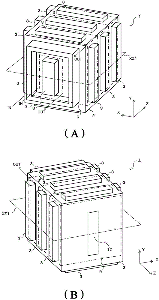
[0055] in figure 1 Of (A), figure 1 In (B), a perspective view showing the appearance of the plasma source 1 is drawn. in figure 1 (A) and figure 1 In (B), it means that the same plasma source 1 is viewed from different directions. The X-axis, Y-axis, and Z-axis shown in the figure are perpendicular to each other.

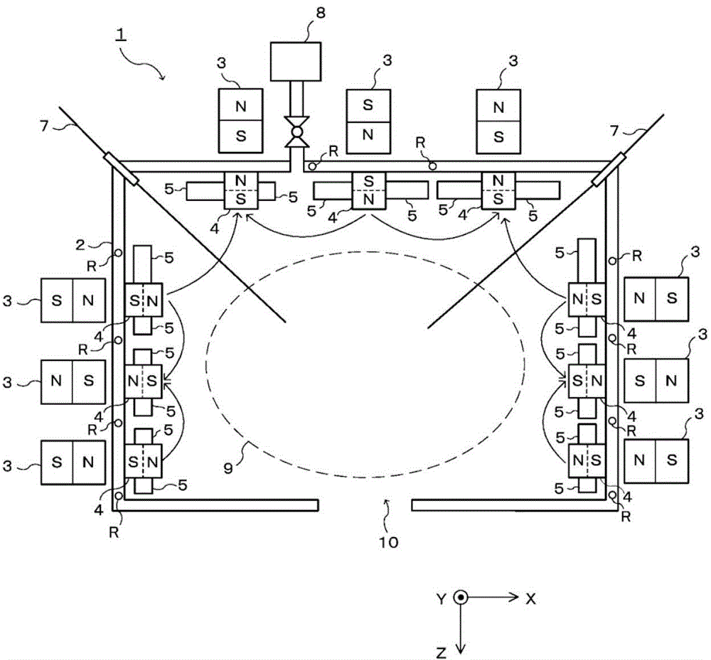
[0056] figure 1 Of (A), figure 1 The plasma generation vessel 2 constituting the plasma source 1 described in (B) has a rectangular parallelepiped shape, and a discharge port 10 is formed on the surface of the plasma generation vessel 2 on the Z direction side. When the ion beam, electron beam, and plasma are drawn from the inside of the plasma source 1 to the outside of the plasma source 1, a plurality of permanent magnets 3 are arranged opposite to each other on the other surface. These permanent magnets 3 generate a cutting magnetic field inside the plasma generation container 2.

[0057] The plurality of permanent magnets 3 that generate a slicing magnetic field a...


PUM


Abstract

The invention provides a plasma source which can prolong an exchange cycle of an adhering prevention plate and improve running rate of the plasma source. The plasma source (1) comprises a plasma generating container (2), the adhering prevention plate (5), a plurality of permanent magnets (3), and a magnet (4). The plasma generating container (2) comprises a cooling mechanism which generates gas used for plasma to guide the gas into the container. The adhering prevention plate (5) is configured on the inner side of the plasma generating container (2). The plurality of permanent magnets (3) are configured on the outer sides of the plasma generating container (2), used to generate cusped magnetic field. The magnet (4) is disposed on the inner side of the plasma generating container (2), and on the position opposite to the permanent magnets (3) and separated with the wall of the plasma generating container (2), the magnet (4) is configured on the inner wall of the plasma generating container (2) in a manner of abutting with the inner wall of the plasma generating container (2).

Description

Technical field [0001] The present invention relates to a plasma source provided with a permanent magnet for blocking plasma, and more particularly to a plasma source provided with an anti-landing plate inside the plasma source. Background technique [0002] Plasma sources are widely used in ion beam irradiation devices, electron beam irradiation devices, plasma doping devices, submerged plasma guns, etc. [0003] For example, in an ion beam irradiation apparatus that irradiates a semiconductor wafer with a positively charged ion beam, an electrode called an extraction electrode is arranged downstream of the plasma source and has a potential more negative than that of the plasma source. This leads to the ion beam. The number of the electrodes is not limited to one. In order to extract the ion beam, there are sometimes multiple electrodes. In this case, these electrodes are called extraction electrode systems. In the ion beam irradiation device, the electrode group or one electro...

Claims


Application Information

Patent Timeline
Patent Type & Authority Patents(China)
IPC IPC(8): H01J27/02
CPCH01J37/08H01J37/32009H01J2229/5682H01J2237/3365H05H1/24
Inventor 井内裕谷井正博
Owner NISSIN ION EQUIP CO LTD
Why Eureka
Try Eureka