Eureka AIR delivers breakthrough ideas for toughest innovation challenges, trusted by R&D personnel around the world.

Ground wire device and laying method

A laying method and technology of ground wires, applied in the direction of connecting contact materials, etc., can solve problems such as fire, electrical equipment tripping or damage, environmental corrosion grounding, etc., and achieve the effect of simple structure and improved grounding reliability

Inactive Publication Date: 2014-05-07
STATE GRID CORP OF CHINA +1
View PDF8 Cites 2 Cited by
  • Summary
  • Abstract
  • Description
  • Claims
  • Application Information

AI Technical Summary

Problems solved by technology

[0002] The combination of grounding device, value grounding wire, and grounding body is also the general term for various grounding electrodes, sibling wires, and grounding leads. The purpose of electrical protection in flammable and explosive places, and many electrical accidents that occur in reality, most of them are caused by grounding defects caused by grounding device laying defects or grounding devices being corroded by the environment after long-term use. The light ones cause power outages due to tripping or damage to electrical equipment, and even cause major accidents such as electric shocks and fires in severe cases. Therefore, a grounding device with high reliability, corrosion resistance and good conductivity and corresponding grounding devices are needed Laying method to meet the needs of safe electricity use

Method used


Image

  • Ground wire device and laying method
  • Ground wire device and laying method

Examples


Embodiment 1

[0019] Embodiment 1: two ground wire devices with a length of 2 meters are laid vertically in advance, and its specific laying method is as follows:

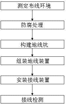
[0020] Step 1: Determine the wiring environment. There are high-rise buildings at the laying point of the ground wire device and the high-rise building is equipped with a lightning rod system. The soil at the laying point is weakly alkaline and the content of metal minerals is negligible;

[0021] The second step: anti-corrosion treatment, spray epoxy resin anti-corrosion coating on the outer surface of the wire, sleeve, sealing ring and ground terminal for anti-corrosion treatment, and the sleeve is a PVC profile tube;

[0022] Step 3: Construct the ground pit, and construct the ground pit according to the number of ground wire devices and the environment of the laying point. The distance between the two ground pits is 5 meters, and the distance between the ground pit and the building is 4 meters, and the distance from the groun...

Embodiment 2

[0026] Embodiment two: Pre-lay two ground wire devices with a length of 2 meters vertically, and its specific laying method is as follows:

[0027] Step 1: Determine the wiring environment. The laying point of the ground wire device is open and there are no high-rise buildings and high-rise buildings and other electrical equipment. close to the road;

[0028] The second step: anti-corrosion treatment, spraying epoxy resin anti-corrosion coating on the outer surface of the wire, bushing, sealing ring and grounding terminal for anti-corrosion treatment, wherein the bushing is galvanized steel pipe;

[0029] The third step: construct the ground pit, and construct the ground pit according to the number of ground wire devices and the environment of the laying point, and the distance between the two ground pits is 5 meters;

[0030] Step 4: Assemble the grounding wire device, assemble the anti-corrosion-treated wire, sleeve, sealing ring and grounding terminal, fill the sealing rin...


PUM


Abstract

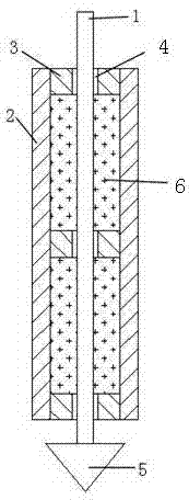
The invention discloses a ground wire device and a laying method. The ground wire device is composed of a wire, a sleeve, sealing rings, a moisture-proof packing material and a grounding terminal, wherein the number of the sealing rings is at least three, the middle of the sealing ring is provided with a threading hole, the sealing rings are uniformly distributed in the sleeve from one end of the sleeve, two sealing rings in the sleeve are provided with the moisture-proof material therebetween, the wire penetrates through the threading hole and is fixed in the sleeve, the lower end of the wire is welded with the grounding terminal, the grounding terminal is in the shape of a cone, the vertex of the cone faces downward, and the area of the cone base is at least three times of the cross sectional area of the wire. The laying method comprises the steps of measuring a wiring environment, carrying out preservative treatment, constructing a ground wire pit, assembling the ground wire device, installing the ground wire device, detecting wire connection, and the like. Compared with a traditional ground wire device, the ground wire device disclosed by the invention has the characteristics that that the structure is simple, the layer is standard, the conductive performance between the grounding device and the ground is good, and the corrosion resistance is strong, thereby greatly improving the grounding reliability of electrical equipment, and laying a good foundation for safe electricity utilization.

Description

technical field [0001] The invention relates to a ground wire device and a laying method, belonging to the technical field of electric power protection. Background technique [0002] The combination of grounding device, value grounding wire, and grounding body is also the general term for various grounding electrodes, sibling wires, and grounding leads. The purpose of electrical protection in flammable and explosive places, and many electrical accidents that occur in reality, most of them are caused by grounding defects caused by grounding device laying defects or grounding devices being corroded by the environment after long-term use. The light ones cause power outages due to tripping or damage to electrical equipment, and even cause major accidents such as electric shocks and fires in severe cases. Therefore, a grounding device with high reliability, corrosion resistance and good conductivity and corresponding grounding devices are needed Laying methods to meet the needs ...

Claims


Application Information

Patent Timeline
Patent Type & Authority Applications(China)
IPC IPC(8): H01R4/66
Inventor 王春生王文华
Owner STATE GRID CORP OF CHINA
Why Eureka
Eureka Blog
Learn More