Light-luring broad-spectrum multi-layer power grid high-efficiency insecticidal lamp

An insecticidal lamp and power grid technology, which is applied to devices, applications, and animal husbandry for capturing or killing insects. , Improve the effect of secondary killing and insecticidal efficiency

Inactive Publication Date: 2014-05-14
江苏鑫田电子科技有限公司
View PDF8 Cites 5 Cited by
  • Summary
  • Abstract
  • Description
  • Claims
  • Application Information

AI Technical Summary

Problems solved by technology

The insecticidal light source of this kind of insecticidal lamp is an incandescent lamp or a fluorescent lamp, and the insecticidal method is to kill insects with a power grid. This kind of insecticidal lamp can only kill some pests, and the insecticidal effect is not ideal. According to the latest research results on the phototaxis of pests, The applicant has carefully studied and analyzed the existing insecticidal lamps, and believes that the existing insecticidal lamps mainly have the following shortcomings:
[0003] First, the spectrum of the light source for attracting insects is unreasonable. The spectrum of the light source is not targeted at attracting pests, and the attracting power of pests is not strong. At the same time, due to the different types of pests caused by different plants, the types of pests in different periods are not completely the same. , and different pests only have aggregation for the corresponding spectrum, and the uniform light source for attracting insects cannot attract all pests, which is one of the main reasons for the poor insecticidal effect
[0004] Second, due to the large distance between the positive and negative electrode grid lines of the insecticidal grid on the existing insecticidal lamp, it can only kill large individual pests, and does not have lethality for small individual pests whose body length is smaller than the electrode spacing , if the distance between the electrodes is reduced, arc discharge is likely to occur between the positive and negative electrodes. To reduce the voltage difference between the positive and negative electrodes, it lacks lethality for large individual pests, which leads to the insecticidal effect of insecticidal lamps. Another major cause of unsatisfactory
[0005] Third, the existing insecticidal lamps lack a structure that forces pests to stay and fly in the lamps for a long time. To the positive and negative poles of the power grid, the pests are likely to fly away, which reduces the chance of killing the pests

Method used


Image

  • Light-luring broad-spectrum multi-layer power grid high-efficiency insecticidal lamp
  • Light-luring broad-spectrum multi-layer power grid high-efficiency insecticidal lamp
  • Light-luring broad-spectrum multi-layer power grid high-efficiency insecticidal lamp

Examples


Embodiment 1

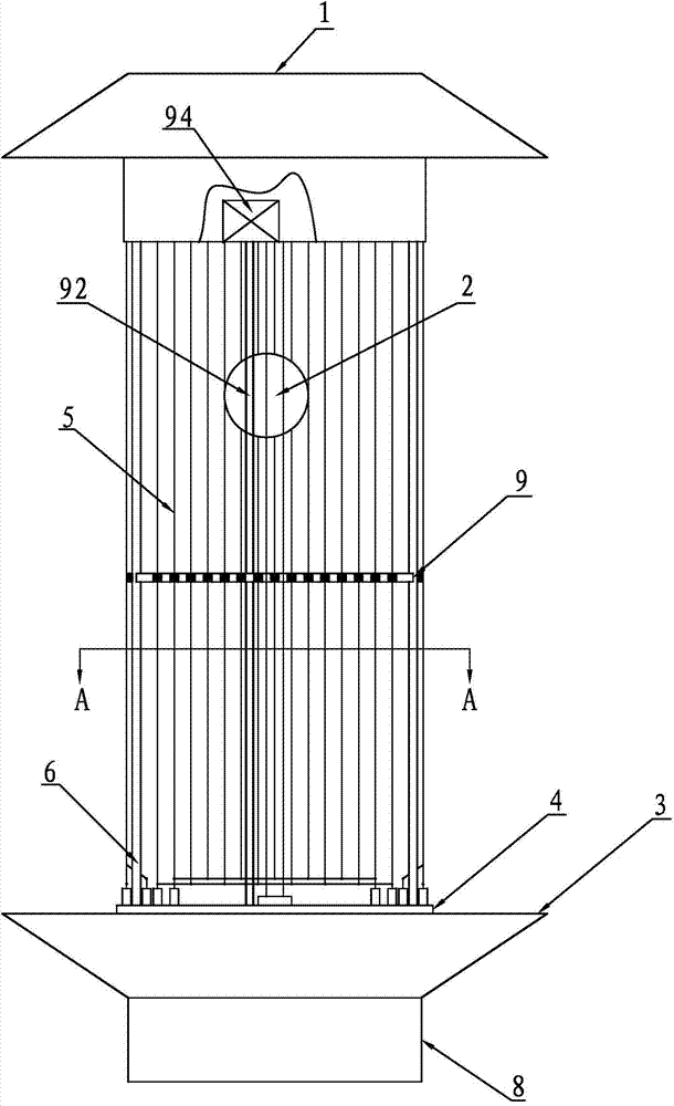
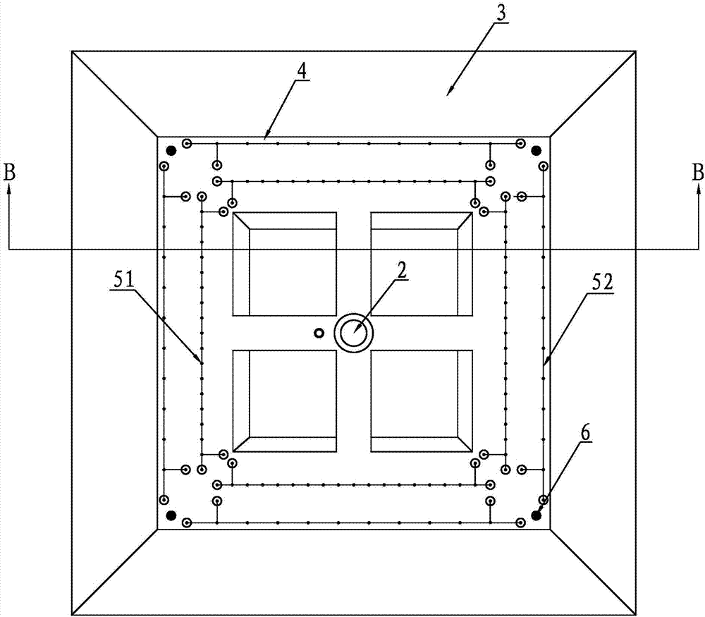
[0028] A kind of high-efficiency insecticidal lamp for light-induced Guangpu multilayer grid, such as Figure 1~3 As shown, it includes a lamp cap 1, a dimming insect lamp 2, an insect collecting shell 3, a base plate 4, an insecticidal power grid 5 and a connecting column 6. A closed box is provided at the lower end of the lamp cap 1 for installation and control The circuit board is protected from rain and short circuit. The base plate 4 is fixed above the insect-collecting shell 3. The combination of the base plate 4 and the insect-collecting shell 3 is connected to the lamp cap 1 through the connecting column 6 to form a frame, which is dimmed The insect lamp 2 is installed between the base plate 4 and the lower end of the lamp cap 1, and is electrically connected to the control circuit board. The wavelength of the variable light insect lamp 2 is determined according to the light color people set to trap and kill insects. In this example A purple fluorescent lamp with a wave...

Embodiment 2

[0030] On the basis of embodiment 1, a fluke blower 7 is installed on the side of the lower cylinder of the insect collecting shell 3, such as Figure 4 As shown, the air inlet of the trematodes fan 7 is connected with the outlet of the insect collecting housing 3, the air outlet of the trematodes fan 7 is connected to the outside world, and the insect collecting box 8 is connected below the outlet of the insect collecting housing 3. The box 8 is provided with an insect-killing pond 81, and an overflow hole 82 is provided on the upper side of the insect-killing pond 81 to control the depth of liquid stored in the insect-killing pond 81. The suction force and the self-gravity of the pests fall into the pest control tank 81 of the insect box 8 and are forced to drown. An overflow hole 82 is provided on the side wall of the upper end of the pest control tank 81 to facilitate rainwater entry Then it will automatically flow out to ensure the depth of the liquid in the pest control ta...


PUM


Abstract

Provided is a light-luring broad-spectrum multi-layer power grid high-efficiency insecticidal lamp. The light-luring broad-spectrum multi-layer power grid high-efficiency insecticidal lamp comprises a lamp cover, a light-changing pest luring lamp, a pest collecting shell, a base plate, an insecticidal power grid ring and connecting columns, wherein the base plate is fixed to the top of the pest collecting shell, a combination body formed by the base plate and the pest collecting shell is connected with the lamp cover to form a frame through the connecting columns, the light-changing pest luring lamp is installed between the base plate and the lower end of the lamp cover, the insecticidal power grid ring is arranged between the base plate and the lower end face of the lamp cover, the light-changing pest luring lamp is arranged in the insecticidal power grid ring, the insecticidal power grid ring is of a multi-layer spaced distribution structure, and encloses the light-changing pest luring lamp, the number of the distributed layers of the insecticidal power grid ring is larger than or equal to two, the separation distance between a positive electrode wire and a negative electrode wire of the portion, arranged in the inner layer, of the insecticidal power grid ring ranges from 1.5 millimeters to 5 millimeters, the separation distance between a positive electrode wire and a negative electrode wire of the portion, arranged in the outer layer, of the insecticidal power grid ring ranges from 5 millimeters to 10 millimeters, and the light colors of the light-changing pest luring lamp can be selected and set according to the favor of pests to be killed; due to the fact that the multi-layer power grid mode is used for killing the pests, the number of the killed pests is large, and the killing range of the individual pests is wide.

Description

Technical field: [0001] The invention relates to the technical field of insecticidal and insecticidal lamp light, in particular to an insecticidal lamp. Background technique: [0002] With the improvement of people's awareness of environmental protection and health, people are paying more and more attention to physical insecticide. Substituting physical insecticide for chemical insecticide is the future development direction. Light trapping and killing insect pests is an important technical means for integrated physical pest control. In recent years, because people only pay attention to plant yield and appearance quality, large amounts of chemical pesticides must be used in the planting process. Although the yield and appearance quality of plants have been improved, they will cause serious damage to environmental elements such as soil and water systems. Excessive levels of chemical residues in the obtained plants will directly affect people's health. With the continuous improvem...

Claims


Application Information

Patent Timeline
Patent Type & Authority Applications(China)
IPC IPC(8): A01M1/04A01M1/22
Inventor 李建明凌和平狄留霞
Owner 江苏鑫田电子科技有限公司
Why Eureka
Try Eureka