Electro-hydraulic composite braking system hierarchical control structure and method of integrated braking cylinder

An electro-hydraulic composite, brake master cylinder technology, applied in the direction of brake transmission, brake, transportation and packaging, can solve the problems such as the inability to apply the structure of the integrated master cylinder electro-hydraulic composite brake system, and achieve scalability and reliability. Good applicability

Active Publication Date: 2014-05-14
TONGJI UNIV
View PDF7 Cites 9 Cited by
  • Summary
  • Abstract
  • Description
  • Claims
  • Application Information

AI Technical Summary

Problems solved by technology

[0006] Most of the above system control methods are aimed at the respective brake system structures, and cannot be applied to the proposed electro-hydraulic composite brake system structure using an integrated master cylinder. Therefore, an electro-hydraulic brake system suitable for an integrated master cylinder is proposed. Layered control architecture and control method of compound braking system

Method used


Image

  • Electro-hydraulic composite braking system hierarchical control structure and method of integrated braking cylinder
  • Electro-hydraulic composite braking system hierarchical control structure and method of integrated braking cylinder

Examples


Embodiment

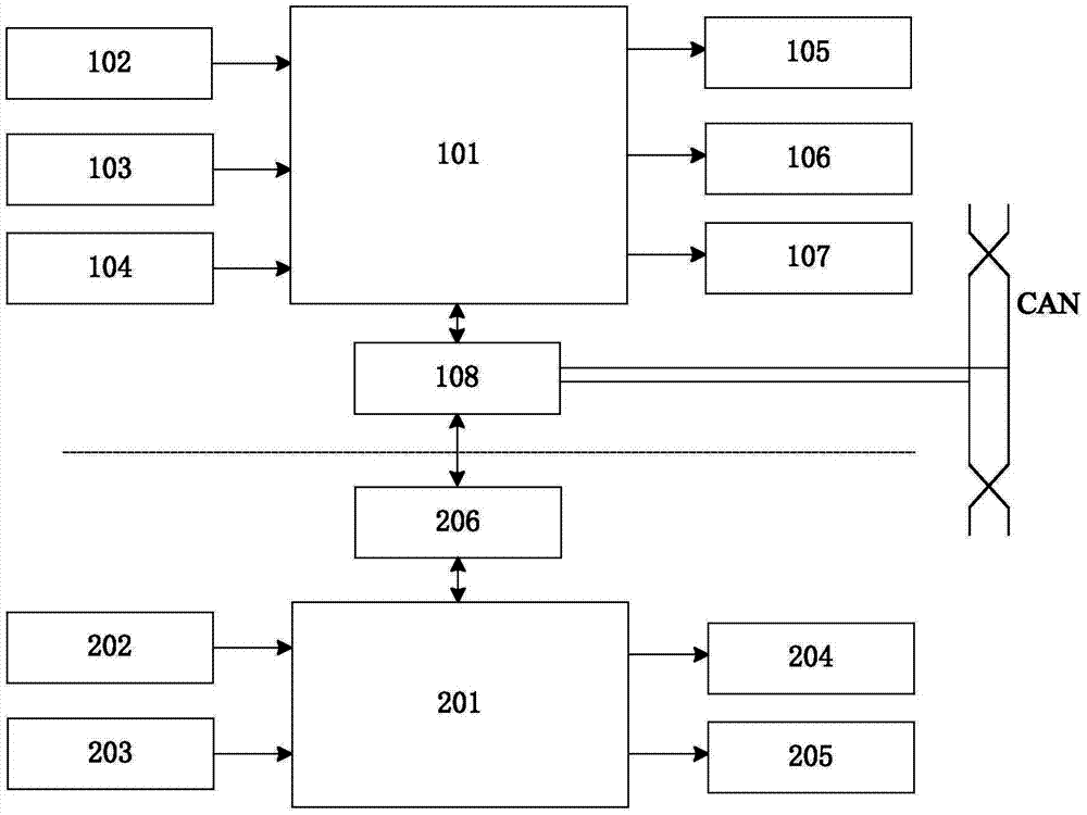
[0051] The hierarchical control architecture of the electro-hydraulic composite brake system suitable for the integrated brake master cylinder, its structure is as follows: figure 1 As shown, it includes the upper electro-hydraulic compound brake control unit and the lower hydraulic control unit.

[0052] The upper electro-hydraulic brake control unit consists of an analog processing circuit 102, a digital processing circuit 103, a power supply module 104, a microprocessor 101, a pump driving circuit 105, a valve driving circuit 106, a status indicator 107 and a communication module 108. The analog quantity processing circuit 102, the digital quantity processing circuit 103, the power supply module 104 input signals to the microprocessor 101, and the microprocessor 101 supplies the pump driving circuit 105, the valve driving circuit 106, the state indication 107, the communication module 108 and the microprocessor 101 Connect and exchange information with the lower hydraulic c...


PUM


Abstract

The invention relates to an electro-hydraulic composite braking system hierarchical control structure and method suitable for an integrated braking cylinder. The hierarchical control structure comprises an upper layer electro-hydraulic composite braking control unit and a lower layer hydraulic control unit. The upper layer electro-hydraulic composite braking control unit is in communication with the lower layer hydraulic control unit through a whole vehicle control system, the current running state of a vehicle is obtained, braking force distribution and stability control are achieved, needed wheel cylinder target pressure is sent to a lower layer hydraulic adjusting unit for real-time adjusting, and wheel cylinder practical pressure is sent to the upper layer electro-hydraulic composite braking control unit. Control system modularization is achieved, hierarchical design is achieved, software and hardware independent design, debugging, installing and testing are convenient, vehicle stability control can be integrated, the structure can be combined with regeneration braking to form an electro-hydraulic composite braking system, and the structure and the method can be widely suitable for braking systems of a pure electric vehicle, a hybrid power vehicle and a fuel cell vehicle.

Description

technical field [0001] The invention relates to a control framework and method of an automobile braking system, in particular to a layered control framework and control method of an electro-hydraulic composite braking system suitable for an integrated brake master cylinder. Background technique [0002] The powertrain of new energy vehicles such as pure electric vehicles, hybrid electric vehicles and fuel cell electric vehicles all use the motor-battery as the core to form an electric drive system. Kinetic energy recovery function. The use of regenerative braking can effectively recover the energy originally dissipated as heat energy during vehicle braking, and improve the energy utilization efficiency, fuel economy and emission performance of new energy vehicles. Since the motor feedback braking torque is limited by the external characteristics of the motor and the charging characteristics of the battery, it cannot meet the vehicle braking requirements on roads with high a...

Claims


Application Information

Patent Timeline
Patent Type & Authority Applications(China)
IPC IPC(8): B60T8/60B60T8/17B60T13/58B60T13/68
Inventor 孙泽昌刘杨冀文斌
Owner TONGJI UNIV
Why Eureka
Try Eureka