Tiny angle measuring device and method based on vision detecting technology

A micro-angle, visual detection technology, applied in the direction of measuring devices, optical devices, instruments, etc., can solve the problems of slow system response speed and small angle measurement range, and achieve the effect of large field of view and wide range detection.

Active Publication Date: 2014-05-14
HARBIN INST OF TECH
View PDF4 Cites 18 Cited by
  • Summary
  • Abstract
  • Description
  • Claims
  • Application Information

AI Technical Summary

Problems solved by technology

[0011] The purpose of the present invention is to solve the problems of small angle measurement range and slow system response speed existing in traditional photoelectric autocollimators, and provide a small angle measurement device and method based on visual detection technology

Method used


Image

  • Tiny angle measuring device and method based on vision detecting technology
  • Tiny angle measuring device and method based on vision detecting technology
  • Tiny angle measuring device and method based on vision detecting technology

Examples


specific Embodiment approach 1

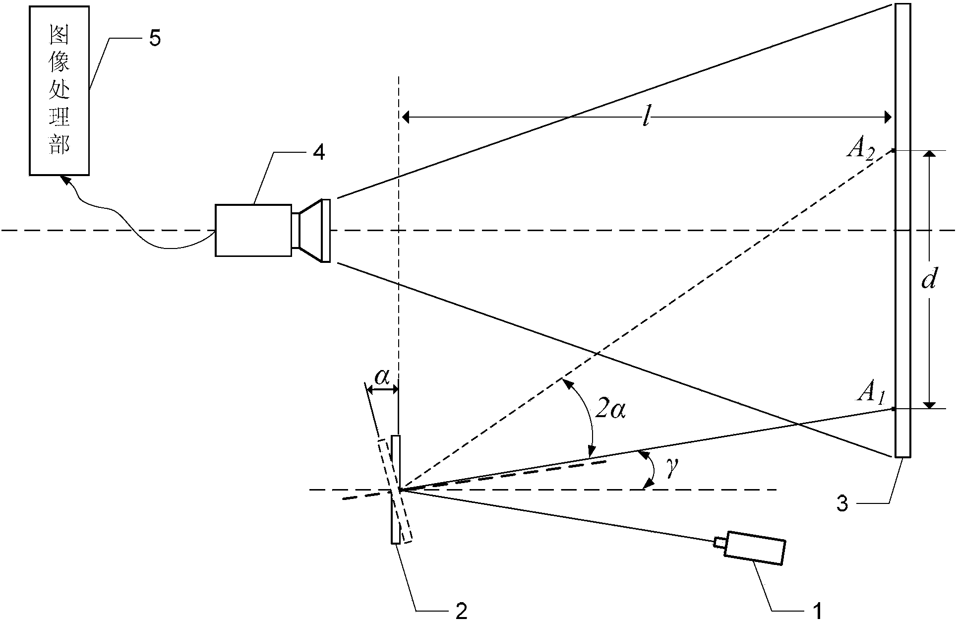
[0027] Specific implementation mode one: the following combination figure 2 Describe this embodiment, the tiny angle measuring device based on visual detection technology described in this embodiment, it comprises laser device 1, measured mirror 2, diffuse reflection projection screen 3, high-speed CCD camera 4 and image processing unit 5;

[0028] The collimated and shaped laser beam emitted by the laser 1 is incident on the mirror surface of the measured reflector 2, and the reflected light reflected by the measured reflector 2 is projected onto the diffuse reflection projection screen 3, and forms a diffuse reflection spot. The diffuse reflection light spot is collected by the high-speed CCD camera 4 and converted into an electrical signal. The electrical signal output end of the high-speed CCD camera 4 is connected with the electrical signal input end of the image processing unit 5, and the diffuse reflection light spot is projected by the image processing unit 5 according...

specific Embodiment approach 2

[0030] Embodiment 2: In this embodiment, Embodiment 1 is further described. The laser 1 is a green laser with a power of 5 mW-10 mW, a divergence angle not greater than 0.5 mrad, and a wavelength of 532 nm.

specific Embodiment approach 3

[0031] Specific embodiment three: this embodiment will further explain embodiment one. The diffuse reflection projection screen 3 is spliced ​​by 30 pieces of 1000mm×500mm×3mm frosted glass, the overall area is 10m×3m, and the rear surface is sprayed with black paint to eliminate 2 reflective. The flatness of a single glass is better than 0.5mm, the joint between glass plates is less than 1mm, the flatness of the overall glass curtain wall is better than 1mm, and the verticality with the ground is better than 0.2°.

[0032] l=50m.

[0033] In this embodiment, the angular deflection of the measured reflector 2 is converted into the displacement movement of the light spot on the diffuse reflection projection screen 3 through the laser 1 and the diffuse reflection projection screen 3 . The high-speed CCD camera 4 and the image processing unit 5 measure and calculate the displacement of the light spot on the projection screen 3 , and then deduce the deflection angle of the measur...


PUM


Abstract

The invention belongs to the field of optics and relates to a tiny angle measuring device and method based on a vision detecting technology. The problem that a traditional photoelectricity autocollimator is small in angle measuring range and low in system response speed is solved. According to the scheme, collimated laser beams sent by a laser device go into a mirror face of a tested reflector, reflected light rays reflected by the tested reflector are projected to a diffuse reflection projection screen, and diffuse reflection light spots are formed, the diffuse reflection light spots are collected by a high-speed CCD camera and are converted into electric signals, an electric signal output end of the high-speed CCD camera is connected with an electric signal input end of an image processing part, the image processing part obtains the tiny angle alpha generated by the tested reflector according to the linear displacement d of the diffuse reflection light spots on the diffuse reflection projection screen, and the linear displacement d is the distance between the diffuse reflection light spots during angle deviation and standard light spots when no angle deviation happens.

Description

technical field [0001] The invention relates to a micro-angle optical measuring device, which belongs to the field of optics. Background technique [0002] With the continuous development of information technology, laser communication between satellites plays an increasingly important role, which has a series of advantages such as large range, fast speed, and accurate transmission. Since the two interstellar satellites are far apart, in order to ensure the alignment of the laser beam and the precise transmission of information, the alignment error of the laser optical axes of the two satellites must be controlled within 10μrad (2 arc seconds). To this end, high-precision angle measurement is required for the small rotation angle of the mirror that controls the direction of the optical axis. [0003] At the same time, the micro-angular displacement detection technology is of great significance in the field of modern precision measurement. Through the high-precision measurem...

Claims


Application Information

Patent Timeline
Patent Type & Authority Applications(China)
IPC IPC(8): G01B11/26
Inventor 陈刚郭玉波孟繁擘叶东于潇宇赵挣庆
Owner HARBIN INST OF TECH
Why Eureka
Try Eureka