Annular truss-type large space foldable mechanism

A truss-type, large-scale technology, applied in the direction of folding antennas, antenna supports/installation devices, etc., can solve the problems of increased folding ratio, high processing and assembly costs, and no large and complex space expandable mechanism, etc., to achieve an improved folding ratio , High performance, easy to drive by single motor

Active Publication Date: 2014-05-14
HARBIN INST OF TECH SHENZHEN GRADUATE SCHOOL
View PDF7 Cites 45 Cited by
  • Summary
  • Abstract
  • Description
  • Claims
  • Application Information

AI Technical Summary

Problems solved by technology

This scheme is simple to unfold and has a single driving source, but due to the presence of multiple sets of bevel gear meshes, the cost of processing and assembly is relatively high, and the folding ratio of this scheme needs to be improved
Relevant scientific research institutions in my country have carried out a series of forward-looking research work on spatially expandable mechanisms and achieved certain results, but no large-scale and complex spatially expandable mechanisms have been put into application yet.

Method used


Image

  • Annular truss-type large space foldable mechanism
  • Annular truss-type large space foldable mechanism
  • Annular truss-type large space foldable mechanism

Examples


Embodiment 1

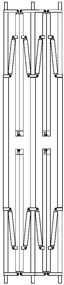
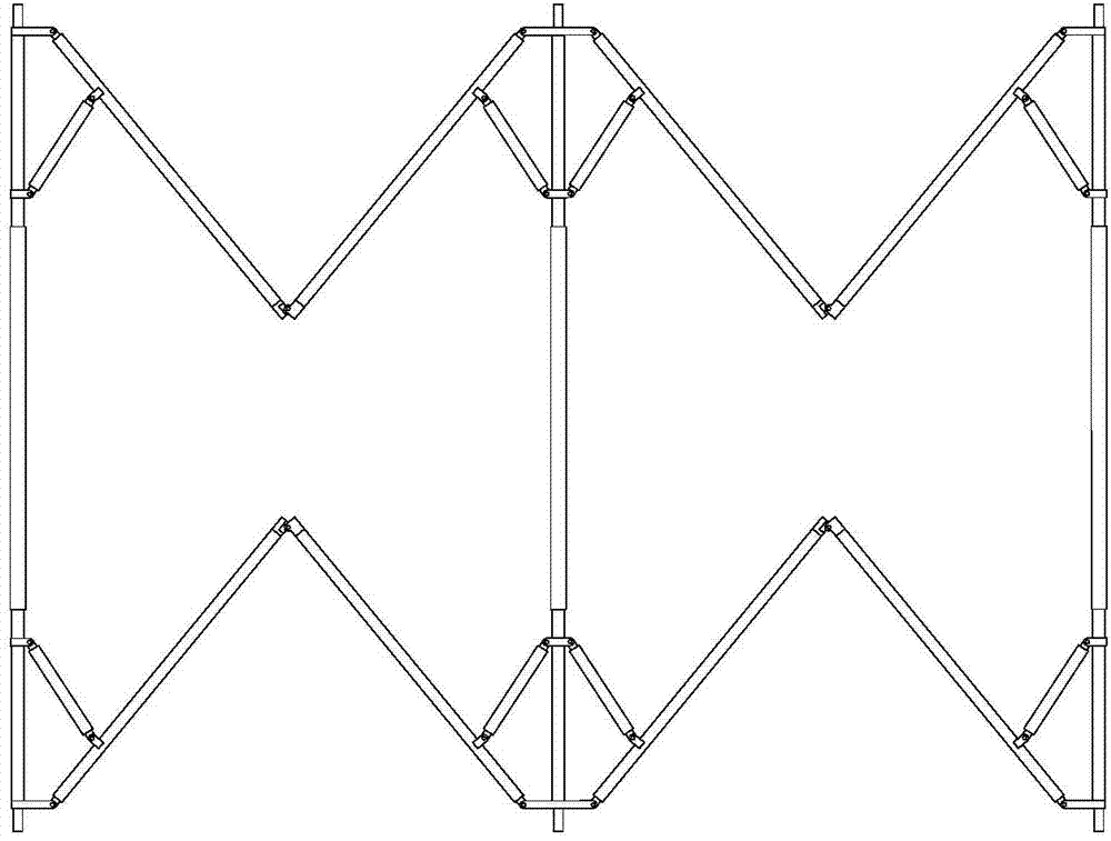
[0036] Such as Figure 7-Figure 10 As shown, the ring-shaped truss-type large-scale space expandable mechanism of this embodiment consists of several (12) identical 6R mechanism expandable units connected end to end to form a ring.

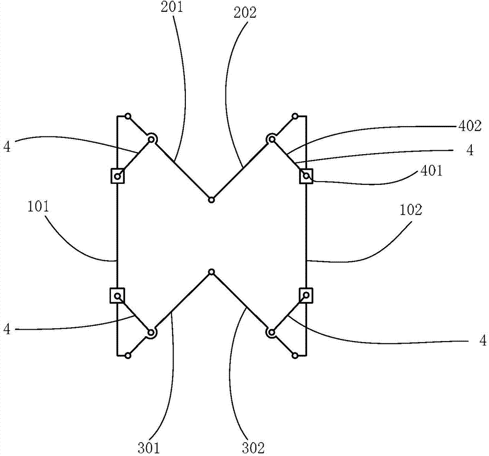
[0037] Such as figure 1 As shown, the expandable unit of the 6R mechanism is symmetrical up and down and left and right, which includes:

[0038] Two identical support rods 101, 102, the two support rods 101, 102 are longitudinally arranged in parallel; the upper end and the lower end of the support rods have a bending part formed by bending vertically inward, and the chord is connected to the bending part through a rotating pair the end.

[0039] Four identical chords, which include two upper chords 201, 202 and two lower chords 301, 302; the starting ends of the two upper chords 201, 202 are respectively connected to the upper ends of the two support rods 101, 102 through the rotating pair; The ends of the two upper chords 201, 202 are connec...

Embodiment 2

[0048] The difference between this embodiment and Embodiment 1 lies in: the synchronous deployment of all the expandable units of the 6R mechanism is realized through the drive of the torsion spring. Figure 11 It is a schematic diagram of the layout of the torsion spring drive mode. Such as Figure 11 As shown, high-torque torsion springs are respectively installed at the rotating joints A, B, C, and D between the chords of the mechanism. The torsion springs are coaxial with the rotating joints, and the two ends are respectively fixed on the rods on both sides of the joints. The two ropes are staggered as shown in the figure, one end is connected to the displacement compensation spring, and the other end is connected to the motor drive end. When the mechanism is in the folded state, the torsion spring is in the compressed state, and the output torque is the largest. When the mechanism is unlocked, the upper and lower chords start to unfold under the action of the torque of ...


PUM


Abstract

The invention provides an annular truss-type large space foldable mechanism which is formed by connecting a plurality of identical 6R mechanism foldable units in an end-to-end mode and in an annular mode. The 6R mechanism foldable units can be symmetrical in the longitudinal direction and in the transverse direction. Each 6R mechanism foldable unit comprises two identical supporting rods and four identical chord members, wherein the two supporting rods are longitudinally arranged in parallel; the four chord members include two upper chord members and two lower chord members, the starting ends of the two upper chord members are connected to the upper ends of the two supporting rods through a revolute pair respectively, the tail ends of the two upper chord members are mutually connected through a revolute pair, the starting ends of the two lower chord members are connected to the lower ends of the supporting rods through a revolute pair respectively, the tail ends of the two lower chord members are mutually connected through a revolute pair, each chord member is movably connected with the adjacent supporting rod through a sliding block crank mechanism, sliding blocks are arranged on the supporting rods in a sleeved mode, one end of each crank is connected with the corresponding chord member through a revolute pair, the other end of each crank is connected with the corresponding sliding block through a revolute pair, and the length of the supporting rods is more than twice that of the chord members. The annular truss-type large space foldable mechanism has a high foldable ratio.

Description

technical field [0001] The invention belongs to the technical field of aerospace equipment and equipment, and relates to an annular truss-type single-degree-of-freedom mechanism, which can be used for satellite parabolic antennas and large space reflector support trusses. Background technique [0002] With the rapid development of satellite communication, deep space exploration, and earth observation technology, the application requirements for aerospace agencies have become more and more urgent. The size of the actually required spaceflight mechanism is getting bigger and bigger, and the precision is getting higher and higher. However, due to the limitation of the carrying space of the space vehicle, it is required that the spaceflight mechanism must be folded and folded in the fairing during the launch stage. After entering the orbit, it will be deployed to the working state by its own power source. The space expandable mechanism has the function of repeatable expansion a...

Claims


Application Information

Patent Timeline
IPC IPC(8): H01Q1/08H01Q1/12
Inventor 李兵齐晓志黄海林邓宗全
Owner HARBIN INST OF TECH SHENZHEN GRADUATE SCHOOL
Why Eureka
Try Eureka