Stability control circuit for injection locking opto-electronic oscillator

A stability control, photoelectric oscillator technology, applied in circuits, lasers, laser parts, etc., can solve the problems of complex structure and high energy consumption

Inactive Publication Date: 2014-05-14
HUNAN INST OF TECH
View PDF0 Cites 6 Cited by
  • Summary
  • Abstract
  • Description
  • Claims
  • Application Information

AI Technical Summary

Problems solved by technology

At this stage, constant temperature control and shock absorption are commonly used at home and abroad to control the long-term stability of OEO. This method has a complicated structure and consumes a lot of energy; some researchers also use the method of compensating for optical fiber delay fluctuations in the optical domain. , this kind of scheme has not been out of the laboratory so far

Method used


Image

  • Stability control circuit for injection locking opto-electronic oscillator
  • Stability control circuit for injection locking opto-electronic oscillator

Examples


Embodiment 1

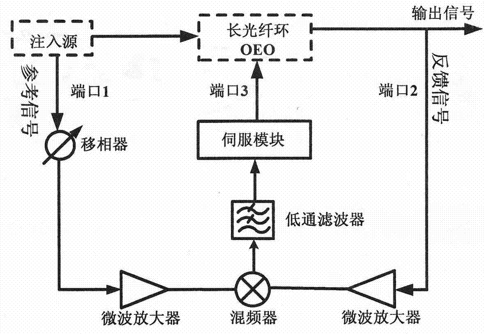
[0020] Such as figure 1 As shown, a stability control circuit for an injection-locked optoelectronic oscillator includes a phase shifter, a microwave amplifier, a mixer, a low-pass filter, and a servo module; where the phase shifter is used to 90-degree the reference microwave signal Phase shifting to achieve the purpose of mixing and phase discrimination; microwave amplifiers are used to amplify the reference signal and feedback signal to saturate the mixer and suppress the amplitude noise of the mixer; the microwave reference after 90-degree phase shifting is realized by using the mixer Source and feedback signal phase discrimination; low-pass filter is used to low-pass filter the baseband signal after phase discrimination, and suppress the high-frequency component after mixing; the servo module includes a signal amplification part and a feedback signal stabilization part, and the signal amplification part is for weak The voltage signal is amplified, and the feedback signal ...

Embodiment 2

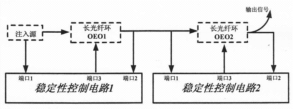
[0024] Such as figure 2 As shown, a stability control circuit for an injection-locked optoelectronic oscillator uses two stability control circuits to control the stability of the secondary injection-locked OEO; the phase noise of the long-loop OEO output signal and the phase noise of the injected signal Related, the lower the phase noise of the injected signal, the better the lower phase noise output of the long-ring OEO. Multiple injections are used to further reduce the phase noise of the injected signal. figure 2 The shown is the secondary injection-locked OEO structure. A stable injection source is used to inject and lock the long optical fiber ring OEO1, combined with a stability control circuit to achieve a stable, single-mode, low-phase noise secondary injection source, and then inject and lock the long optical fiber ring OEO2, combined with the second stability control circuit, finally achieves a stable, single-mode, lower phase noise output signal.

[0025] Utiliz...


PUM


Abstract

The invention provides a stability control circuit for an injection locking opto-electronic oscillator. The stability control circuit for the injection locking opto-electronic oscillator comprises a phase shifter microwave amplifier, a frequency mixer, a low-pass filter and a servo module, and is characterized in that an injection signal is divided by the stability control circuit into two parts, one part of the injection signal is injected into a long fiber loop OEO, the other part of the injection signal serves as a reference signal, 90-degree phase shifting is carried out on the reference signal, then, frequency mixing and phase demodulation are carried out on the reference signal and an OEO output signal, a voltage signal processed through phase demodulation is fed back to the voltage control end of a voltage control phase shifter in an OEO loop, the phase of an oscillation signal is controlled through phase shifting of the phase shifter until the oscillation signal and the reference signal are synchronous, and finally a stable output signal is obtained. According to the stability control circuit for the injection locking opto-electronic oscillator, long-term stability of the OEO can be kept on the situation that complex external factor interference exists; compared with a traditional OEO stability control circuit, signal processing is carried out in an electric field, complexity of an optical domain control system is overcome, and high control accuracy is achieved.

Description

technical field [0001] The invention relates to a stability control circuit for an injection-locked opto-electronic oscillator (OEO), which belongs to the field of microwave photonics in optical communication and microwave / millimeter wave technology, in particular to an injection-locked opto-electronic oscillator stability control circuit. Background technique [0002] Over the past 20 years, with the rapid development of microwave photonic technology, optoelectronic oscillators (OEO) have attracted widespread attention. A considerable number of research institutions and researchers at home and abroad are engaged in OEO or related research. OEO is characterized by its distinctive features have been impressively developed. [0003] The earliest OEO structure in the world was proposed by Neyer and Voges in 1982, which uses the ring structure of the electro-optic modulator controlled by the optical signal feedback at the output end to realize the oscillator. The structure pro...

Claims


Application Information

Patent Timeline
Patent Type & Authority Applications(China)
IPC IPC(8): H01S3/13
Inventor 洪俊姚胜兴张松华严亚周
Owner HUNAN INST OF TECH
Why Eureka
Try Eureka