Supercharge Your Innovation With Domain-Expert AI Agents!

A tool nozzle and its manufacturing method

A nozzle and tool technology, which is applied to the tool nozzle mechanism and its manufacturing field, can solve the problems of inability to clean at a fixed point, prolonged production tact, and inability to fully guarantee the cleanliness of water channels.

Inactive Publication Date: 2015-12-16
SAIC-GM-WULING AUTOMOBILE CO LTD
View PDF9 Cites 0 Cited by
  • Summary
  • Abstract
  • Description
  • Claims
  • Application Information

AI Technical Summary

Problems solved by technology

[0003] The cooling channel holes around the combustion chamber of the cylinder head of the engine are small and deep. In order to ensure the cleanliness of the water channel holes, in the prior art, the finishing tool nozzle T179 of op140 adopts a single hole, and the cleaning route follows a zigzag line to clean the cylinder. Covered waterway holes, this type of cleaning can basically guarantee the cleanliness of the waterway, but because the waterway holes are distributed along the circumference of the combustion chamber, the current tool nozzles can be cleaned but cannot be cleaned at fixed points, and the cleanliness of the waterway cannot be fully guaranteed
Moreover, this cleaning method has a relatively long tool path, which leads to an extended production cycle. Currently, the cycle time of OP140 is 172s, while the cycle time of T179 accounts for 31s, accounting for 18% of the cycle time.

Method used


Image

  • A tool nozzle and its manufacturing method

Examples


Embodiment Construction

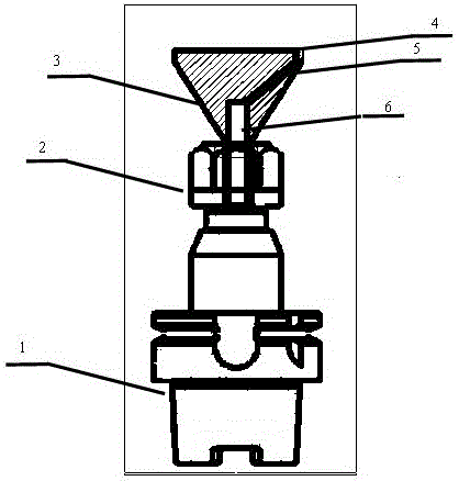
[0022] Below in conjunction with accompanying drawing, preferred embodiment of the present invention is described in further detail:

[0023] Such as figure 1 As shown, a new type of tool nozzle includes a main shaft and a nozzle main body 3, and a handle 1 embedded with the main shaft. A tool seat 2 is arranged between the main body of the spray head 3 and the tool handle 1. Interference fit with the bottom end of the nozzle body 3; the nozzle body 3 is provided with a water outlet hole 4 for cleaning, and a process hole 5 is also arranged below the water outlet hole 4, and the nozzle body 3 is provided with a The process hole 5 communicates with the central hole 6 .

[0024] The new tool nozzle is placed in the tool magazine in a similar way to the tool. When not in use, it is positioned on the tool head by the tool holder. It needs to be placed on the spindle by changing the tool in the NC program. The jaws at the front end of the spindle and The tail of the new tool nozz...


PUM

PropertyMeasurementUnit
diameteraaaaaaaaaa

Abstract

The invention provides a cutting tool nozzle and a manufacturing method of the cutting tool nozzle. The cutting tool nozzle comprises a main shaft, a nozzle body and a cutting tool handle, wherein the cutting tool handle and the main shaft are embedded; a cutting tool holder is arranged between the nozzle body and the cutting tool handle; the cutting tool holder and the bottom end of the nozzle body are in interference fit; the nozzle body is provided with a water outlet hole used for cleaning; an auxiliary hole is formed below the water outlet hole; the nozzle body is further provided with a center hole communicated with the auxiliary hole. The feed path of the cutting tool nozzle is changed, the fold line path of a prior cutting tool nozzle is replaced with the linear path of the cutting tool nozzle, the feed time is shortened, and the production efficiency is improved.

Description

technical field [0001] The invention relates to a tool nozzle and a manufacturing method thereof, in particular to a tool nozzle mechanism for cleaning an automobile engine and a manufacturing method thereof. Background technique [0002] As the heart of a car, the engine has very high requirements for the precision and cleanliness of its components. Therefore, when machining the cylinder block and head of the engine, we need to ensure the cleanliness of its surface and interior. The cleaning machine can ensure good surface cleanliness, but The cleanliness of the interior needs to be cleaned with a nozzle to meet the requirements. [0003] The cooling channel holes around the combustion chamber of the cylinder head of the engine are small and deep. In order to ensure the cleanliness of the water channel holes, in the prior art, the tool spray nozzle T179 of finishing op140 adopts a single hole, and the cleaning route follows a zigzag line to clean the cylinder. Covered wate...

Claims


Application Information

Patent Timeline
Patent Type & Authority Patents(China)
IPC IPC(8): B08B3/02B05B1/14B05B15/06B23P15/00
CPCB05B1/14B08B3/024B23P15/00
Inventor 甄朝敬孙爱民陆贤辉
Owner SAIC-GM-WULING AUTOMOBILE CO LTD
Features
  • R&D
  • Intellectual Property
  • Life Sciences
  • Materials
  • Tech Scout
  • Unparalleled Data Quality
  • Higher Quality Content
  • 60% Fewer Hallucinations
Learn More