Aluminum alloy extrusion asymmetric porous mould

A porous mold, asymmetric technology, applied in the direction of metal extrusion mold, metal material coating process, solid diffusion coating, etc., can solve the problems of large difference in flow rate, high scrap rate, uneven wall thickness of profiles, etc. Achieve excellent hardness, increase hardness, and good stability

Active Publication Date: 2014-05-21
ALNAN ALUMINIUM CO LTD
View PDF7 Cites 3 Cited by
  • Summary
  • Abstract
  • Description
  • Claims
  • Application Information

AI Technical Summary

Problems solved by technology

However, due to reasons such as the size of the section of the aluminum alloy profile matching the tonnage of the extruder, some porous dies can only be designed as asymmetrical porous dies.
At present, the aluminum profiles produced by asymmetric porous molds designed by many manufacturers have defects such as uneven wall thickness, large difference in flow speed, and high scrap rate.

Method used


Image

  • Aluminum alloy extrusion asymmetric porous mould
  • Aluminum alloy extrusion asymmetric porous mould
  • Aluminum alloy extrusion asymmetric porous mould

Examples


Embodiment 1

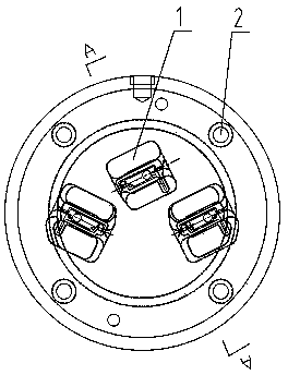
[0034] see as Figure 1-7 As shown, the present invention includes a shunt hole 1, a bolt 2, a discharge hole 3, a mold pad 4, a lower mold 5, a mold core 6, an upper mold 7, a shunt bridge 8, a secondary empty knife 9, a primary empty knife 10, Working belt 11, die hole 12, symmetrical die hole 12.1, asymmetrical die hole 12.2 and welding chamber 13, described upper die 7, lower die 5 and die pad 4 are assembled by bolts 2 in sequence, die pad 4 is set There is a discharge hole 3 corresponding to the die hole, and the upper die 7 is provided with a shunt bridge 8 and a shunt hole 1, and one end of the shunt bridge 8 is provided with a mold core 6 and extends into the lower mold 7, and the shunt hole 1 Distributed on both sides of the shunt bridge 8, the lower mold 5 is sequentially provided with a welding chamber 13, a die hole 12, a primary empty knife 10 and a secondary empty knife 9 from the feed end to the discharge end, and the welding chamber 13 is set at the lower par...

Embodiment 2

[0038] see as Figure 2-8 As shown, the present invention includes a shunt hole 1, a bolt 2, a discharge hole 3, a mold pad 4, a lower mold 5, a mold core 6, an upper mold 7, a shunt bridge 8, a secondary empty knife 9, a primary empty knife 10, Working belt 11, die hole 12, symmetrical die hole 12.1, asymmetrical die hole 12.2 and welding chamber 13, described upper die 7, lower die 5 and die pad 4 are assembled by bolts 2 in sequence, die pad 4 is set There is a discharge hole 3 corresponding to the die hole, and the upper die 7 is provided with a shunt bridge 8 and a shunt hole 1, and one end of the shunt bridge 8 is provided with a mold core 6 and extends into the lower mold 7, and the shunt hole 1 Distributed on both sides of the shunt bridge 8, the lower mold 5 is sequentially provided with a welding chamber 13, a die hole 12, a primary empty knife 10 and a secondary empty knife 9 from the feed end to the discharge end, and the welding chamber 13 is set at the lower par...

Embodiment 3

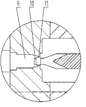
[0042] see as Figure 2-7 , 9, the present invention includes a shunt hole 1, a bolt 2, a discharge hole 3, a mold pad 4, a lower mold 5, a mold core 6, an upper mold 7, a shunt bridge 8, a secondary empty knife 9, and a first-level empty knife 10. Working belt 11, die hole 12, symmetrical die hole 12.1, asymmetrical die hole 12.2 and welding chamber 13. The upper die 7, lower die 5 and die pad 4 are assembled by bolts 2 in sequence. The die pad 4 is provided with a discharge hole 3 corresponding to the die hole, the upper die 7 is provided with a shunt bridge 8 and a shunt hole 1, and one end of the shunt bridge 8 is provided with a mold core 6 and extends into the lower die 7 Among them, the distribution holes 1 are distributed on both sides of the distribution bridge 8, and the lower mold 5 is sequentially provided with a welding chamber 13, a die hole 12, a first-level empty knife 10 and a second-level empty knife from the feed end to the discharge end. 9. The welding cha...


PUM


Abstract

The invention discloses an aluminum alloy extrusion asymmetric porous mould. The aluminum alloy extrusion asymmetric porous mould comprises an upper mould, a lower mould and a mould cushion, wherein the upper mould, the lower mould and the mould cushion are assembled with one another through bolts, and the mould cushion is provided with a discharging hole which corresponds to the mould hole. The aluminum alloy extrusion asymmetric porous mould is characterized in that the upper mould is provided with a flow dividing bridge and flow dividing holes, one end of the flow dividing bridge is provided with a mould core and extends into the lower mould, the flow dividing holes are distributed at two sides of the flow dividing bridge; the lower mould is sequentially provided with a welding room, a mould hole, a first-stage hollow knife and a second-stage hollow knife from a charging end to a discharging end; the welding room is arranged under the flow dividing holes, and the inner wall of the mould hole is a work belt. The aluminum alloy extrusion asymmetric porous mould can be used for producing the aluminum alloy sectional material which is even in wall thickness, even in flow speed, and more than 85% in comprehensive yield, and the mould has the characteristic of higher stability during production.

Description

technical field [0001] The invention relates to the field of aluminum alloy extrusion die processing, in particular to an aluminum alloy extrusion asymmetric porous die. Background technique [0002] Aluminum alloy has good extrusion formability, light specific gravity, good strength, corrosion resistance, good economy, environmental protection and recyclability, etc. It is widely used in industry, electronics, construction and other fields. Processing is mostly done through hot extrusion dies. [0003] Mold processing has a series of advantages such as high production efficiency, good quality, material saving and low cost. Hot work die steel is an important type of die material. Since hot work dies work at high temperatures for a long time, their structure will change as the service time prolongs, and their performance will change accordingly. Therefore, this requires Hot work die steel has good strength and toughness, cold and heat fatigue performance and high temperatur...

Claims


Application Information

Patent Timeline
Patent Type & Authority Applications(China)
IPC IPC(8): B21C25/02C22C38/46C23C8/38
Inventor 朱建成刘羽飞陈资平陈荣立
Owner ALNAN ALUMINIUM CO LTD
Why Eureka
Try Eureka