
Flying saucer type helicopter utilizing active airflow to generate lifting power

Inactive Publication Date: 2014-05-21
余彦武
View PDF6 Cites 17 Cited by
  • Summary
  • Abstract
  • Description
  • Claims
  • Application Information

AI Technical Summary

Problems solved by technology

First of all, whether it is a single rotor, or a horizontal or tandem dual rotor, whether it is a coaxial reverse propeller helicopter or a tilt rotor aircraft, they all have a common feature, that is, the huge rotor, the exposed high-speed rotating rotor It is very unsafe to collide with any object. This structure greatly increases the requirements of existing helicopters on the openness of space, restricts the operation of helicopters in small spaces, and increases the unsafety of helicopters; secondly , the level flight of existing helicopters is mainly realized by the periodic variable pitch technology. This mechanical operation principle not only has a complex structure, but also brings problems such as large vibration, high noise, and easy failure; thirdly, eliminate In terms of spin, the coaxial anti-rotor technology is of course very good, but most of the current mainstream helicopters still use the tail rotor, which also limits the structural layout of the helicopter and increases the size of the helicopter
It is precisely because of its complexity and insecurity that helicopters are currently mainly used by personnel with professional skills in special fields such as rescue and disaster relief, military, police, geology, and sea, and it is impossible to be as popular as ordinary means of transportation.

Method used


Image

  • Flying saucer type helicopter utilizing active airflow to generate lifting power
  • Flying saucer type helicopter utilizing active airflow to generate lifting power
  • Flying saucer type helicopter utilizing active airflow to generate lifting power

Examples


Embodiment Construction

[0010] The aircraft according to the present invention is not limited to a certain structure, and a typical implementation is introduced here for description.

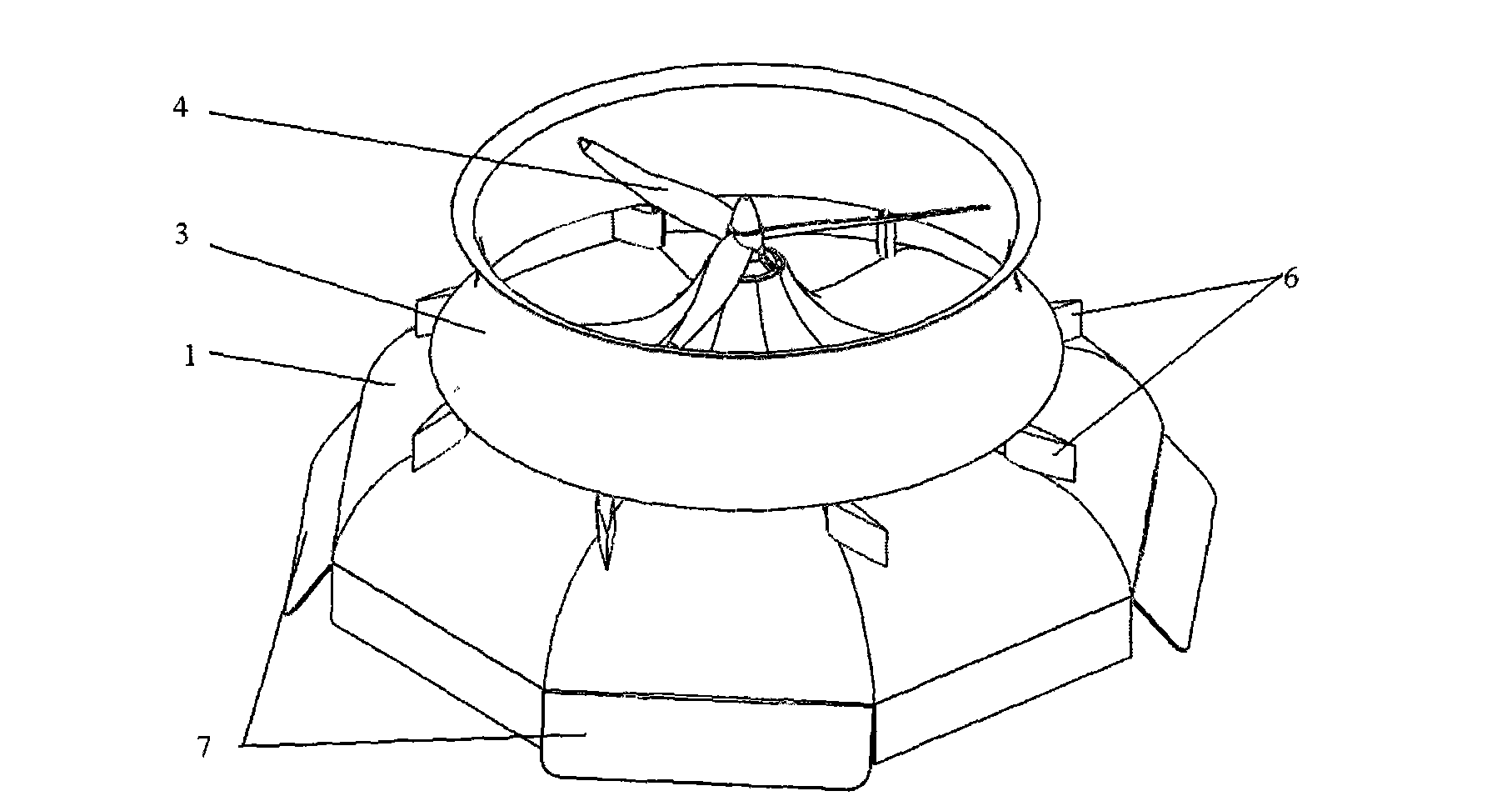
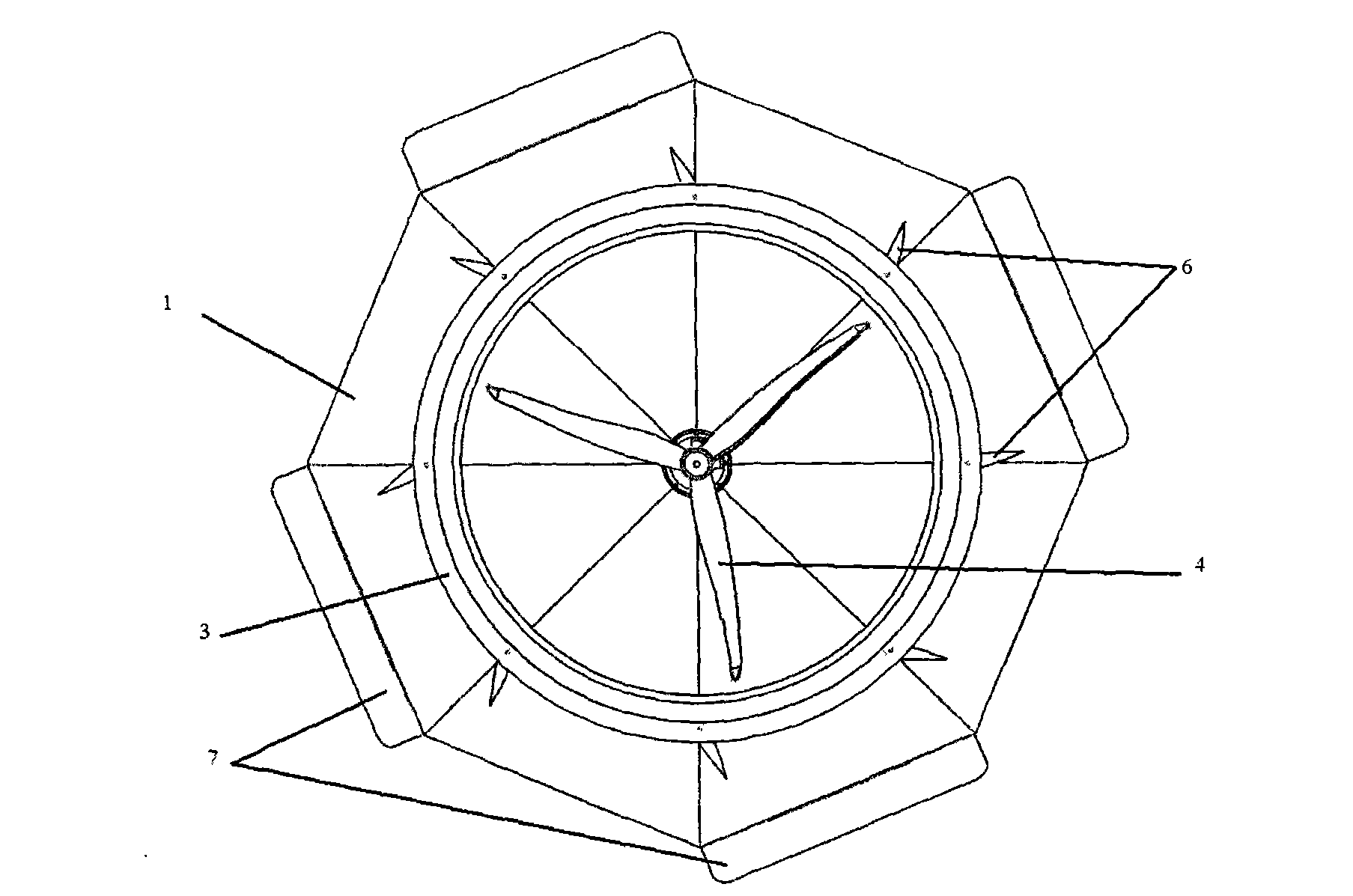
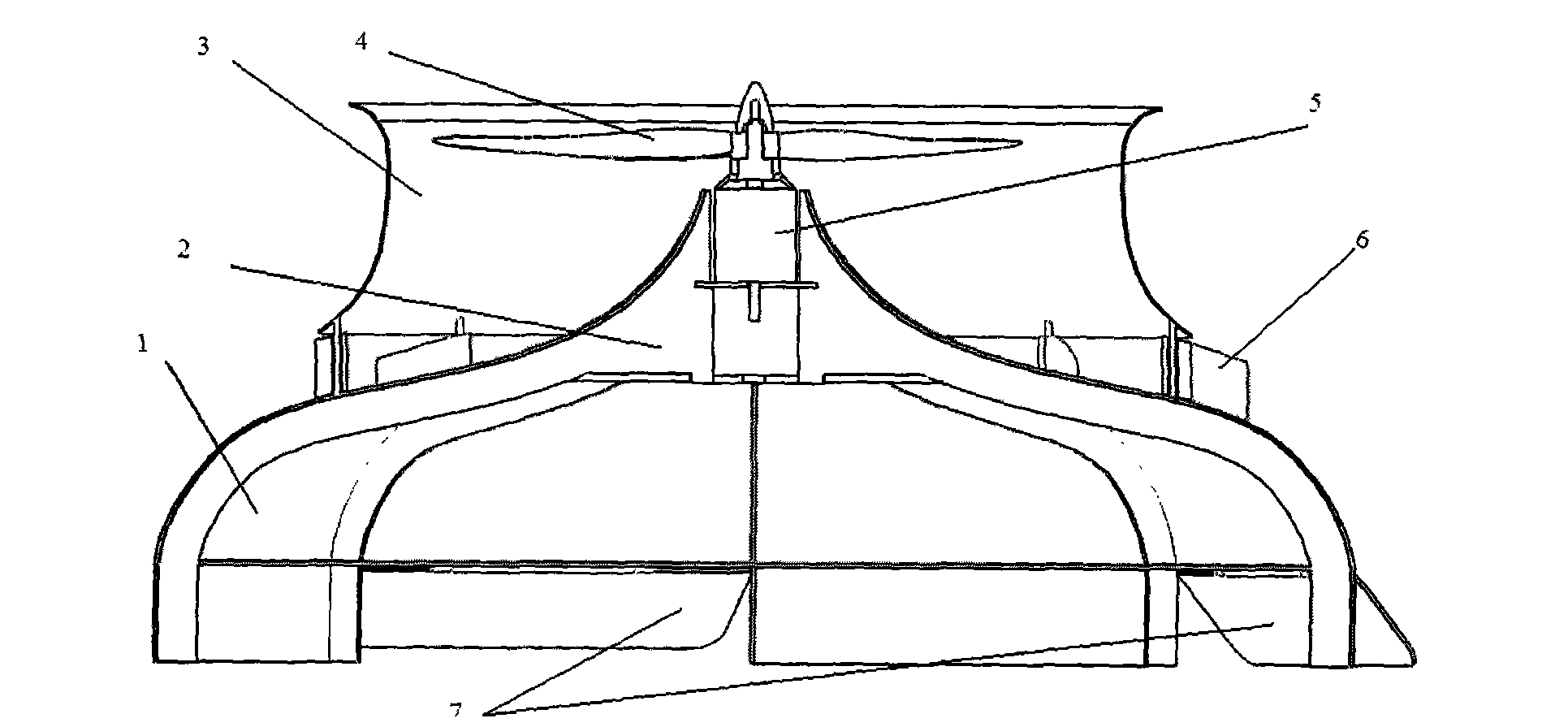
[0011] This aircraft has a butterfly-shaped fuselage 1 whose outer edge is a regular octagon. The fuselage 1 is actually a skin skeleton structure, and its interior is supported by the skeleton 2. The duct 3 is above the fuselage 1. , is fixedly connected with the framework 2, the power unit 5 is installed in the center of the framework 2, and the power unit 5 drives the propeller fan 4 to rotate. The surface flows from the center to the surroundings. At the airflow outlet between the duct 3 and the fuselage 1, eight guide vanes 6 evenly distributed are installed, and the guide vanes 6 can rotate along the vertical axis, and the angle of these blades can be adjusted to control the outflow of the airflow. Direction, using the tangential reverse thrust of the airflow to push the fuselage 1 to rotate in situ, or offset t...


PUM


Abstract

The invention relates to a flying saucer type helicopter utilizing active airflow to generate lifting power. As everyone knows, the asymmetric airflow on the upper surfaces and lower surfaces of wings can generate lifting power, however for both a fixed wing aircraft and a propeller-driven aircraft, the wings move, the air is motionless, and airflow is passively generated. According to the invention, an opposite approach is chosen. Specifically, the wings are fixed, actively generated airflow flows through the upper surfaces of the wings, an air pressure difference is manufactured between the upper surfaces and lower surfaces of the wings so as to generate the lifting power, thus realizing a safe and simple aircraft that can achieve vertical take-off and landing, hovering, level flight and pivot steering. The appearance of the aircraft is similar to a flying saucer. By adjusting the angle between the airflow direction of the aircraft's upper surface and the radial direction, spin of the fuselage can be controlled, and by adjusting the flow velocity distribution of the front, back, left and right directions, the inclination direction of the aircraft body can be changed to realize level flight and direction control. The novel aircraft not only has all the advantages of traditional helicopters, but also has the characteristics of simplicity, compactness, safety, stability and the like, and is an ideal solution to one-man aircrafts and unmanned reconnaissance aerial vehicles.

Description

technical field [0001] The invention belongs to the field of aviation aircraft, in particular to a helicopter or a flying saucer aircraft capable of vertical take-off and landing, hovering and level flight. Background technique [0002] Compared with other means of transportation, the biggest advantage of a helicopter is that it can take off and land vertically and hover in the air, which makes it not need specific roads (relative to cars), airports (relative to fixed-wing aircraft), docks (relative to ships), tracks ( Compared with auxiliary facilities such as trains), it only needs a flat land slightly larger than the size of the fuselage to realize take-off and landing. That is to say, the geographical terrain basically does not constitute any restrictions on the use of helicopters. Helicopters can easily handle deserts and swamps, rivers, lakes and seas that can only be sailed by boats, or cities full of tall buildings. From this point of view, the helicopter is the mos...

Claims


Application Information

Patent Timeline
IPC IPC(8): B64C27/20
Inventor 余彦武刘志军
Owner 余彦武
Learn More