Robotic Bionic Hydraulic System

A hydraulic system and robot technology, applied in the field of bionic hydraulics, can solve problems such as high cost, high operating conditions, and poor flexibility

Active Publication Date: 2015-10-28
安徽莫根智能装备有限公司
View PDF4 Cites 0 Cited by
  • Summary
  • Abstract
  • Description
  • Claims
  • Application Information

AI Technical Summary

Problems solved by technology

Although the advantages of the hydraulic drive itself are still effective at present, the structural form of the traditional hydraulic system has faced obvious bottlenecks to meet the further improvement of bionic robots: 1) Central hydraulic station: fragile and energy-consuming, but redundant Or the cost of protection treatment is high, and once the central hydraulic station is damaged, the whole will be paralyzed; 2) The use of servo valves and proportional valves is costly, and high operating conditions (high or extremely high oil cleanliness requirements) will lead to high failure rates and high Maintenance requirements, and the design principle of the servo valve determines that a considerable amount of hydraulic energy from the central hydraulic pump will be bypassed or overflowed to achieve precise flow or pressure control to complete robot limb movements, and these energy are actually wasted 3) The high-pressure oil pipes are spread all over, many and long, and the loss along the journey caused by pipe resistance is large. It will bring extra difficulty to the design of the robot to a large extent; the probability of its bursting in actual working conditions is also greater; 4) Using piston or plunger hydraulic cylinders as action actuators has limitations not only in obtaining high-speed The high price paid for mobile performance is more reflected in its poor flexibility, which is not conducive to the high-speed running and jumping actions of bionic robots
[0003] Although some of the world's top bionic multi-legged walking robots have performed well in bench tests, if new ideas are not used to fundamentally eliminate these obstacles of traditional hydraulic systems and components, then in order to achieve these excellent functions and Performance, the energy consumption, manufacturing cost and use cost paid lead to the viability and activity of these robots in the wild are not up to people's expected goals

Method used


Image

  • Robotic Bionic Hydraulic System
  • Robotic Bionic Hydraulic System
  • Robotic Bionic Hydraulic System

Examples


Embodiment

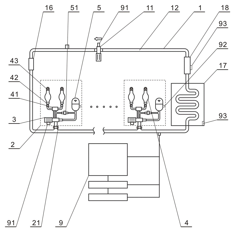
[0032] The present invention is a robot driving system with hydraulic pressure as the driving source, which is used to control and complete various body movements of the robot, such as walking, running, jumping or falling, etc., so that the body movement of the robot can simulate the movement of the human body or animal body and has biomechanical properties.

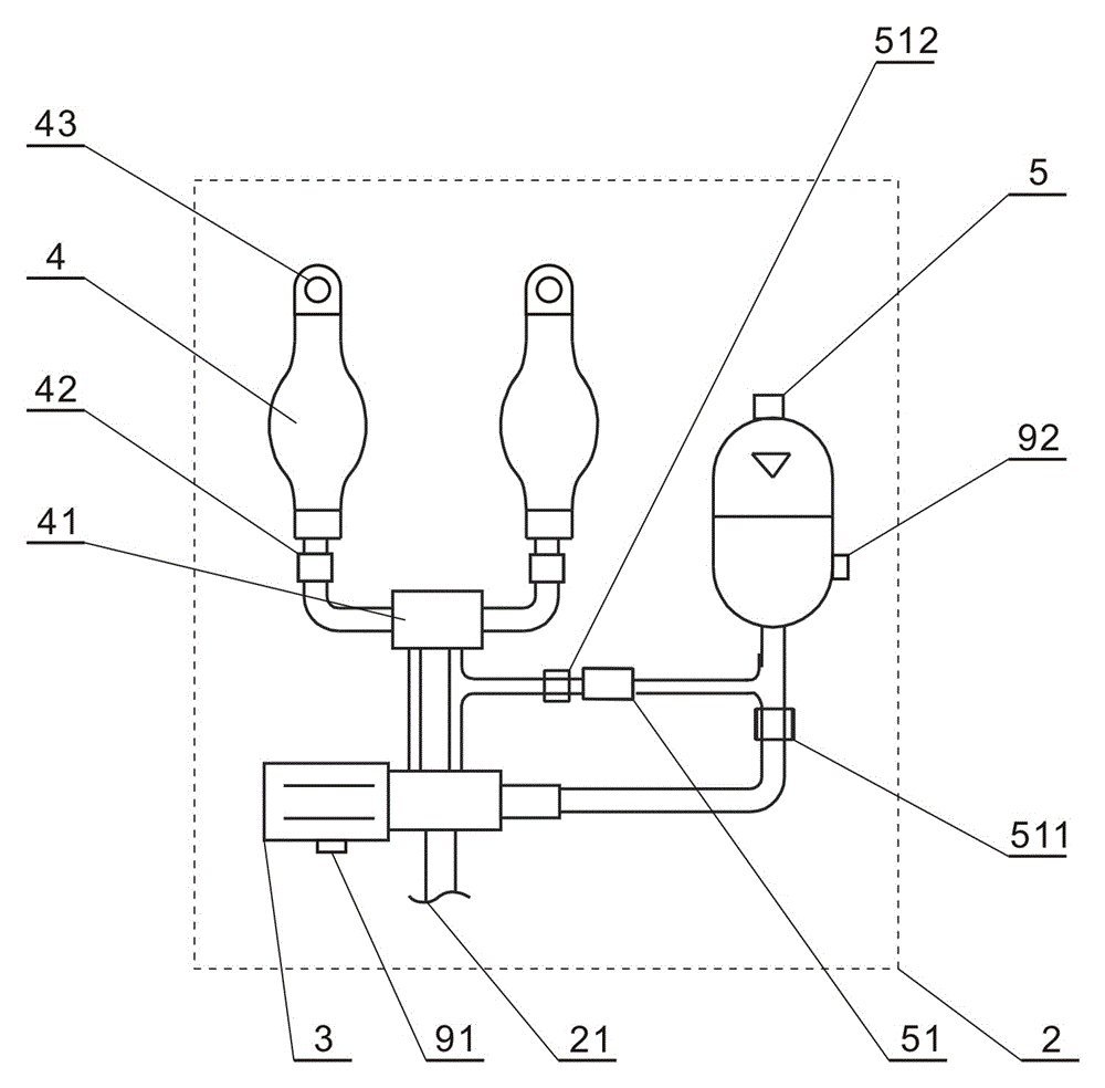
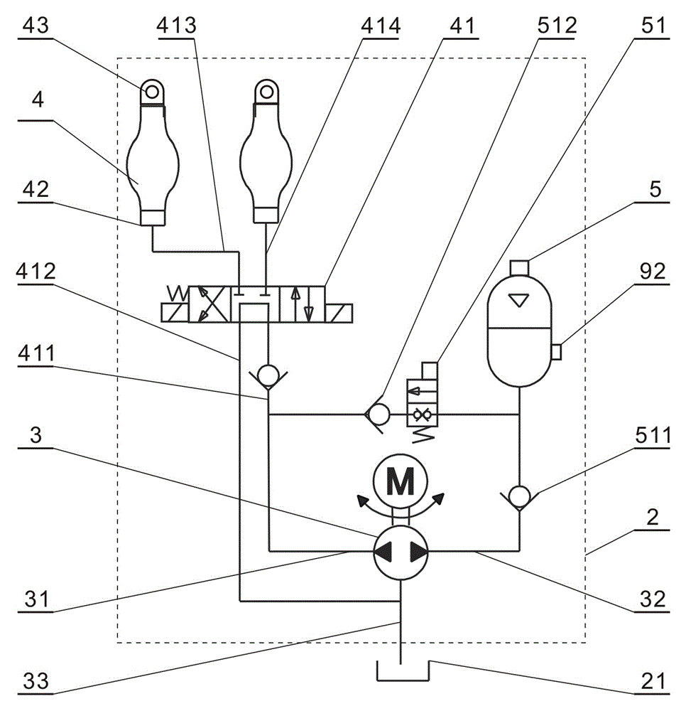
[0033] The composition of the technical solution of the present invention includes a hydraulic oil supply circulation system 1 , several bionic execution units 2 and a CPU central controller 9 .

[0034] The hydraulic oil supply circulation system 1 of the present invention includes an oil delivery pump 11, an oil circuit 12, a filter 16, a temperature regulator 17, an electrostatic oil purifier 18, and a bionic execution unit access point 21. The output end is sequentially connected to the filter 16, the access point 21 of the bionic execution unit, the temperature regulator 17, the electrostatic oil purifier 18, and th...


PUM


Abstract

The invention discloses a robot bionic hydraulic system. The system comprises a hydraulic oil supply circulating system, a plurality of bionic executing units and a CPU (Central Processing Unit) central controller; the bionic executing units are connected to the hydraulic oil supply circulating system; the CPU central controller is connected with the hydraulic oil supply circulating system and controls the hydraulic oil supply circulating system; each bionic executing unit is formed by a micro electro-hydraulic pump, a hydraulic muscle, a three-position four-way reversing valve and a bone energy accumulator. In the invention, according to the actual requirements of a robot, the bionic executing units are switched in and each bionic executing unit correspondingly drives one motion joint of limbs of the robot to control and complete various limb actions of the robot, such as walking, running, jumping or falling, so that the limb actions of the robot can simulate muscle body movement of a human body or an animal body and the robot bionic hydraulic system has the biomechanical characteristic.

Description

technical field [0001] The invention relates to the technical field of bionic hydraulics, a robot with biomechanical characteristics and hydraulic pressure as a driving source for simulating human or animal muscles, in particular a bionic hydraulic system for a robot. Background technique [0002] At present, hydraulic systems are used in more and more designs of bionic multi-legged walking robots in the world. This is because of the technical advantages of hydraulic transmission itself: the driving force is transmitted over long distances through non-rigid connections, which is powerful and durable. However, no matter how advanced the steady-state control, gait control, body bionic structure design and intelligent control system of the bionic multi-legged walking robot driven by the hydraulic system are at present, the design of the hydraulic system used to drive the body movement remains the same. It is based on the structural form of the traditional hydraulic drive system...

Claims


Application Information

Patent Timeline
Patent Type & Authority Patents(China)
IPC IPC(8): F15B21/02F15B15/10F15B1/08B62D57/032
Inventor 何晓飞陆亚卓匡懋萃范秦沛
Owner 安徽莫根智能装备有限公司
Why Eureka
Try Eureka