A combustion chamber fuel injection and mixing device and a combustion chamber comprising the same

A fuel injection and mixing device technology, which is applied in combustion chambers, continuous combustion chambers, combustion methods, etc., can solve problems such as too many swirlers and complex structures, achieve simple and compact structure, prolong service life, and improve carbon deposition prevention performance effect

Active Publication Date: 2016-04-20
AECC COMML AIRCRAFT ENGINE CO LTD
View PDF4 Cites 0 Cited by
  • Summary
  • Abstract
  • Description
  • Claims
  • Application Information

AI Technical Summary

Problems solved by technology

However, the existing staged combustion technology has not been able to solve the contradiction between the NOx emission at the staged state point and the emission performance of CO and UHC in the staged combustion technology. Moreover, too many swirlers are used, resulting in a more complicated structure.

Method used


Image

  • A combustion chamber fuel injection and mixing device and a combustion chamber comprising the same
  • A combustion chamber fuel injection and mixing device and a combustion chamber comprising the same

Examples


Embodiment Construction

[0039] First introduce some terms in this technical field, among them:

[0040] Cyclone: ​​a device that produces a rotating jet of gas;

[0041] Staged combustion: A combustion strategy, divided into axial staged combustion and radial staged combustion, refers to the mixed combustion of fuel and air in different areas, burning in different areas;

[0042] Nozzle: fuel injection and atomization device;

[0043] Fuel atomization: the process of using nozzles to turn liquid fuel into oil droplets;

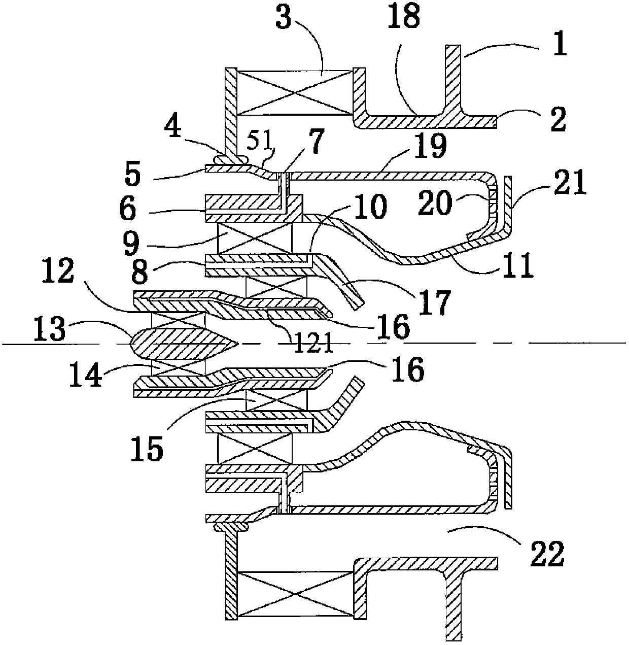
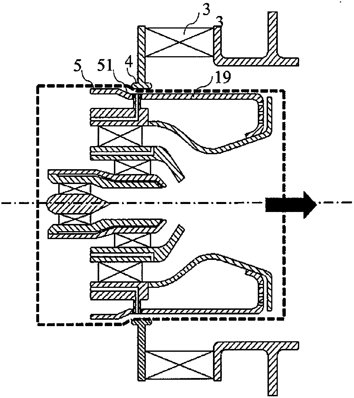
[0044] See figure 1 with figure 2 As shown, the combustion chamber fuel injection and mixing device according to the present invention adopts a fuel injection and oil-air mixing system composed of a fuel nozzle system and a swirler, and is arranged with 3 levels of independent partitioned fuel supply in a centrally graded arrangement. The whole device is connected with the transition section and the splash plate of the end wall of the head end of the flame tube of the combustion chamber by ...


PUM


Abstract

The invention provides a combustion chamber fuel jetting and mixing device. The device comprises a pre-combustion stage, an intermediate stage and a main combustion stage, wherein the pre-combustion stage comprises a central conical body, a first-stage cyclone, a pre-film spray nozzle and a second-stage cyclone; the intermediate stage comprises an intermediate fuel supplying passage, a lining, an intermediate-stage cyclone and a sleeve, and fuel is supplied to a space, between the sleeve and the lining, at the downstream of the intermediate-stage cyclone; the main combustion stage comprises a main fuel supplying passage, a main-combustion-stage internal wall, a main-combustion-stage cyclone and a main-combustion-stage external wall, and the fuel is supplied to a space, between the main-combustion-stage internal wall and the main-combustion-stage external wall, at the downstream of the main-combustion-stage cyclone; the tail end of the main-combustion-stage internal wall and the tail end of the sleeve are connected, a hollow cavity is formed between the sleeve and the main-combustion-stage internal wall, cooling holes are formed in the tail end of the main-combustion-stage internal wall, and upstream air enters the hollow cavity and penetrates through the cooling holes so as to impact the tail end of the sleeve and cool the tail end of the main-combustion-stage internal wall and the tail end of the sleeve. The invention further provides a combustion chamber comprising the device.

Description

Technical field [0001] The invention belongs to the field of energy and power combustion devices, and particularly relates to a fuel injection and mixing device for a combustion chamber of an aviation engine and a combustion chamber including the device. Background technique [0002] As atmospheric environmental issues have received more and more attention worldwide, the requirements for the emission of pollutants from aero engines have become increasingly strict. The market demand for next-generation aero-engine products shows that the emissions of nitrogen oxides (NOx) are reduced by about 50% compared to the current International Civil Aviation Organization (ICAO) standards, while other emissions such as carbon monoxide (CO) and unburned hydrocarbons ( UHC) are lower than the standards set by ICAO. [0003] Studies have shown that controlling the gas temperature in the combustion chamber is the key to controlling NOx pollution emissions. One of the main technical ways to contro...

Claims


Application Information

Patent Timeline
Patent Type & Authority Patents(China)
IPC IPC(8): F23R3/38
Inventor 曾庆林朱英范仁钰
Owner AECC COMML AIRCRAFT ENGINE CO LTD
Why Eureka
Try Eureka