Wavelength signal demodulation method for optical displacement sensor

A displacement sensor and signal demodulation technology, applied in the field of aviation signal processing, can solve the problems of increased time consumption, increased system volume and complexity, large volume and weight, etc., to achieve light weight, increased system volume and complexity, small size effect

Inactive Publication Date: 2014-05-21
FLIGHT AUTOMATIC CONTROL RES INST
View PDF1 Cites 2 Cited by
  • Summary
  • Abstract
  • Description
  • Claims
  • Application Information

AI Technical Summary

Problems solved by technology

In the current research, the wavelength is mostly obtained by using a spectrometer to read the spectral information into the computer, and then use software to process the spectral data to obtain the central wavelength. This method can be used in laboratory research and also meets the general accuracy requirements. There are insurmountable problems in the realization of engineering applications in the control system: the on-board control system generally requires a response frequency above 100Hz, and the spectrometer is an integrating optical instrument, which needs to integrate the optical signal first and then process it. If you want to obtain high resolution, then The amount of collected data must be increased, which leads to a sharp increase in the time spent in data transmission and processing. It usually takes 20-40ms to complete the above integration, collection, transmission, and processing, so that excellent dynamic characteristics cannot be obtained; Aircraft equipment requires small size and light weight, while the spectrometer itself has a large volume and weight, which varies depending on different models, generally above 300g; the spectrometer cannot work without a computer and its operating system, which will inevitably increase the system volume and complexity; the spectrometer It cannot be used under harsh external conditions such as high and low temperature, vibration and dust

Method used


Image

  • Wavelength signal demodulation method for optical displacement sensor
  • Wavelength signal demodulation method for optical displacement sensor
  • Wavelength signal demodulation method for optical displacement sensor

Examples


Embodiment

[0030] A specific embodiment is as follows:

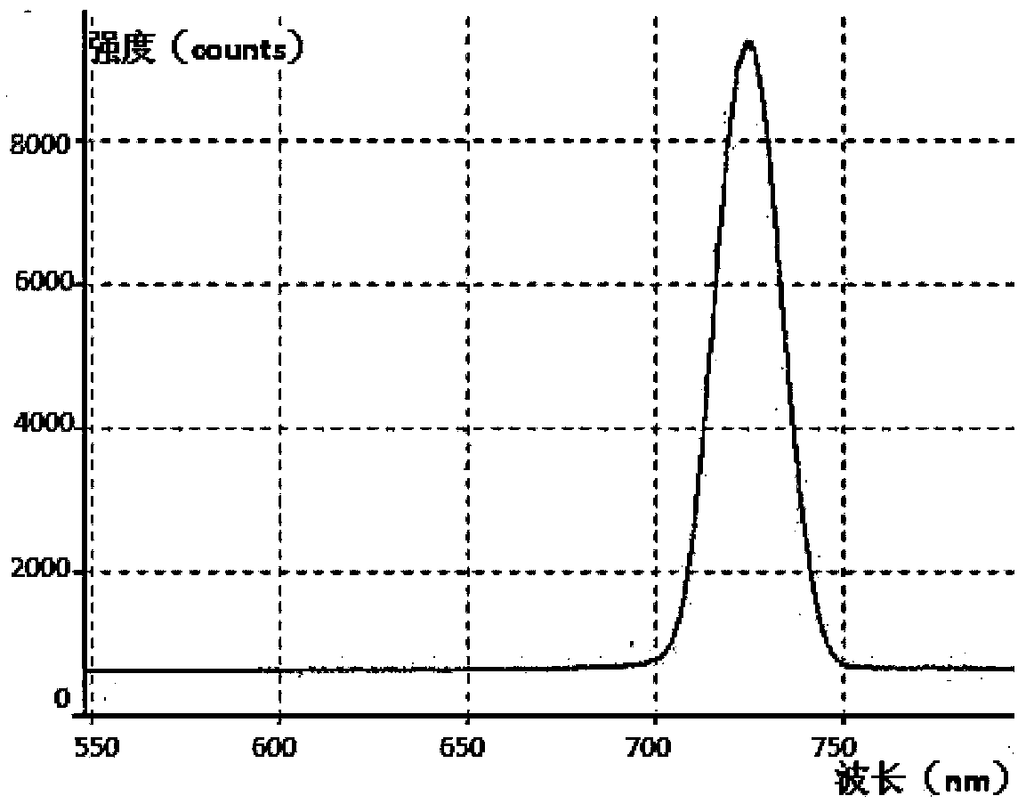
[0031] Step 1: When the optical displacement sensor is located at a certain position, a narrow-band diffracted light is generated, and the spectrum is as follows image 3 As shown, the central wavelength is roughly 724nm, which is transmitted to the color sensitive element by the optical fiber;

[0032] Step 2: The narrow-band diffracted light is input into the color sensitive element WS7.56, and the color sensitive element is excited to generate two induction currents I 1 and I 2 , respectively 0.32mA and 0.1mA;

[0033] Step 3: Select the temperature sensor LM35 and place it next to the color sensitive element WS7.56 within 2mm to sense the temperature change of the color sensitive element WS7.56, and input the logarithmic conversion circuit in the form of voltage V. When the temperature is 25°C, this The voltage value is 0.04mV;

[0034] Step 4: Connect the two induced currents I 1 , I 2 Import the logarithmic conversion c...


PUM


Abstract

The invention relates to a wavelength signal demodulation method for an optical displacement sensor. According to the technical scheme, a color sensitive element which is provided with two different junction depth has different response characteristics to incident light in different wave length, output signals, namely, narrowband diffraction light, of the optical displacement sensor are input to the color sensitive element, the color sensitive element outputs two circuits of response currents, the two circuits of response currents are processed through a logarithmic transformation circuit and then logarithms of a ratio between the two circuits of response currents are obtained, demodulation voltage which is in linear relationship with the wave length is output, the demodulation voltage is conversed into digital values through an A / D converter to be guided into a calculation demodulation module, displacement information can be obtained due to performing interpolation budgeting on the demodulation voltage, and displacement monitoring of the displacement sensor is achieved. The wavelength signal demodulation method for the optical displacement sensor has the advantages of enabling a wavelength signal demodulation system to be small in size and light in weight, being simple in signal processing, rapidly responding to incident light signals, achieving high dynamic displacement monitoring, enabling a temperature compensating circuit to be added and being strong in environmental suitability compared with other demodulation schemes.

Description

technical field [0001] The invention belongs to the field of aviation signal processing, in particular to a wavelength signal demodulation method of an optical displacement sensor. Background technique [0002] With the development of optical transmission flight control technology, the research on optical displacement sensor continues to deepen, and the demodulation of the output signal of optical displacement sensor has become the research focus. The tuning task is to obtain the center wavelength, and then obtain the sensor displacement. In the current research, the wavelength is mostly obtained by using a spectrometer to read the spectral information into the computer, and then use software to process the spectral data to obtain the central wavelength. This method can be used in laboratory research and also meets the general accuracy requirements. There are insurmountable problems in the realization of engineering applications in the control system: the on-board control s...

Claims


Application Information

Patent Timeline
Patent Type & Authority Applications(China)
IPC IPC(8): G01B11/02
Inventor 王东辉张兵韩志华吴忠张超李秉实包艳郑普超
Owner FLIGHT AUTOMATIC CONTROL RES INST
Why Eureka
Try Eureka