
Triaxial integrated optical fiber gyroscope inert measurement device based on optical source cold standby and compensation and installation method

A fiber optic gyroscope and cold backup technology, applied in the field of inertial measurement, can solve problems such as the attitude that cannot provide three-axis inertial space, affect the performance of the fiber optic ring, and affect the performance of the gyroscope.

Active Publication Date: 2014-05-21
BEIJING AEROSPACE TIMES OPTICAL ELECTRONICS TECH
View PDF5 Cites 24 Cited by
  • Summary
  • Abstract
  • Description
  • Claims
  • Application Information

AI Technical Summary

Problems solved by technology

[0004] In the prior art, the fiber optic gyro inertial measurement device mostly adopts the design scheme of three-axis independent work, which can measure the attitude of the spacecraft's three axes relative to the inertial space, but this design scheme does not use redundant design, especially the attenuation of the light source will affect the gyro performance, when any one of the axes fails, it cannot provide the attitude of the three axes relative to the inertial space, and the reliability is low; in addition, the existing optical fiber ring structure adopts a skeleton structure, and this design can be used at high In the low temperature environment, the performance of the fiber ring will be affected due to the asynchronous deformation of the skeleton and the fiber

Method used


Image

  • Triaxial integrated optical fiber gyroscope inert measurement device based on optical source cold standby and compensation and installation method
  • Triaxial integrated optical fiber gyroscope inert measurement device based on optical source cold standby and compensation and installation method
  • Triaxial integrated optical fiber gyroscope inert measurement device based on optical source cold standby and compensation and installation method

Examples


Embodiment Construction

[0048] The present invention will be further described below in conjunction with drawings and embodiments.

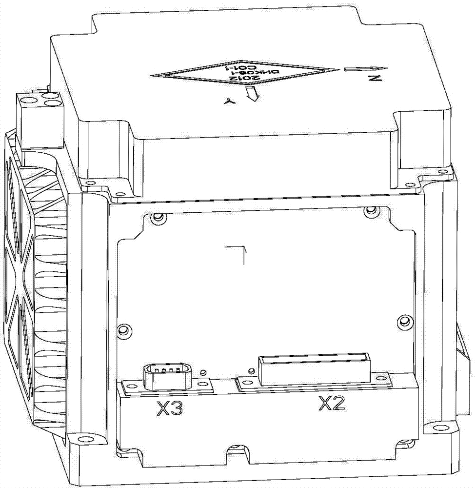
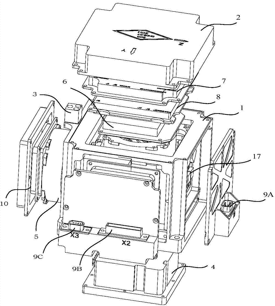
[0049] (1) Overall composition design: fiber optic gyroscope inertial measurement device, such as figure 1 , 2 As shown, it includes a main body 1 and an upper cover 2; on the main body, three skeletonless optical fiber ring heads 5, a system signal processing and interface circuit analog circuit 7, a light source driving and cooling circuit 6, and an upper cover 2 There are system signal processing and interface circuit digital boards 8 inside, gyro signal processing and interface circuit digital boards are respectively housed in the two side covers without connectors, and the remaining gyro signal processing and interface circuit digital boards 8 are installed in two On the side cover of the connector, there is no circuit board on the side cover with a connector, and the interior is an optoelectronic device. A secondary power supply 4 is installed below the main bod...


PUM


Abstract

The invention discloses a triaxial integrated optical fiber gyroscope inert measurement device based on optical source cold standby, and a compensation and installation method. The triaxial integrated optical fiber gyroscope inert measurement device comprises a body, two triaxial shared optical sources, an optical source driving and refrigerating circuit, three framework-free optical fiber loop meter heads, three optical fiber gyroscope signal processing and interference circuit digital boards, a system signal processing and interface circuit digital plate, a secondary power supply module, a frequency and voltage conversion simulation circuit, three electric connectors and a reference mirror. The three optical fiber loops share an optical source, and a standby cold optical source is provided, thus the reliability is high; the installation error correction method used by the invention can effectively reduce the triaxial cross coupling; the circuit boards are installed on a lateral cover and an upper cover for the convenience of radiation protection design; meanwhile, the favorable heat radiation is realized; framework-free optical fiber loops are used, the adaptability of a magnetic environment and a radiation environment is improved.

Description

technical field [0001] The invention relates to a three-axis integrated long-life miniaturized fiber optic gyro inertial measurement device, in particular to a miniaturized, high-reliability, long-life device for spacecraft navigation, guidance and control, and adopts zero-bias compensation and installation error correction methods. The invention relates to a fiber optic gyroscope inertial measurement device, which belongs to the technical field of inertial measurement. Background technique [0002] As a symbol of high-tech development, spacecraft plays an extremely important role in my country's national defense construction. Local wars under high-tech conditions in the future will put forward high requirements on the ability to obtain information. The attitude stability of aerospace is the premise and guarantee for effectively performing various tasks such as aiming and docking. Among them, the inertial instrument is the key to the attitude control system. Key equipment, ...

Claims


Application Information

Patent Timeline
Patent Type & Authority Applications(China)
IPC IPC(8): G01C21/16G01C25/00
CPCG01C21/16G01C25/00G01C25/005
Inventor 杨清生王颂邦刘绍辉冯杰张俊杰王丰苗锋夏金桥田海泉
Owner BEIJING AEROSPACE TIMES OPTICAL ELECTRONICS TECH
Learn More