
Micro-current induction power supply type temperature measuring and alarming device and temperature measuring and alarming method

A technology of inductive power supply and alarm device, which is applied in the direction of circuit devices, signal devices, visible signal devices, etc., can solve the problems of bulky current transformer, troublesome installation, high cost, etc., and achieves convenient long-distance observation, convenient installation, and small small effect

Active Publication Date: 2014-05-21
四川瑞霆智汇科技有限公司 +1
View PDF4 Cites 2 Cited by
  • Summary
  • Abstract
  • Description
  • Claims
  • Application Information

AI Technical Summary

Problems solved by technology

This kind of temperature-sensitive luminous cap uses the principle of current transformer to take power, but the volume of current transformer is relatively large, the installation is very troublesome, and the cost is high, which seriously limits the actual application effect in the field of distribution network equipment and other fields, so it is very difficult Difficult to popularize
In addition, the current transformer is a closed magnetic circuit, because the large current circuit will form a strong electromagnetic field, if there is a closed magnetic circuit, it will cause eddy current loss, and the eddy current loss will cause serious heat generation. The magnetic circuit is closed, so the temperature measuring device that takes power from the current transformer cannot be used in a large current circuit

Method used


Image

  • Micro-current induction power supply type temperature measuring and alarming device and temperature measuring and alarming method
  • Micro-current induction power supply type temperature measuring and alarming device and temperature measuring and alarming method

Examples


Embodiment Construction

[0032] The present invention will be further explained below in conjunction with the drawings:

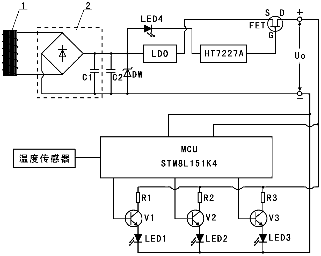
[0033] Such as figure 1 As shown, the micro-current induction power supply type temperature measurement alarm device of the present invention includes an induction power taking circuit and a temperature measurement alarm circuit. The induction power taking circuit provides power for the temperature measurement alarm circuit; the power taking circuit includes a current sensor 1, a rectifier Filter circuit 2, voltage regulator circuit, voltage monitoring chip HT7227A, field effect tube FET, energy storage capacitor C2 and light emitting diode LED4, current sensor 1 is composed of a non-closed magnetic core and a coil wound outside the non-closed magnetic core. The closed magnetic core is superimposed by silicon steel sheets. The coil is an enameled copper wire with a wire diameter of 0.06mm. The number of turns of the coil is 12000. The rectifier filter circuit 2 includes a full bridge r...


PUM


Abstract

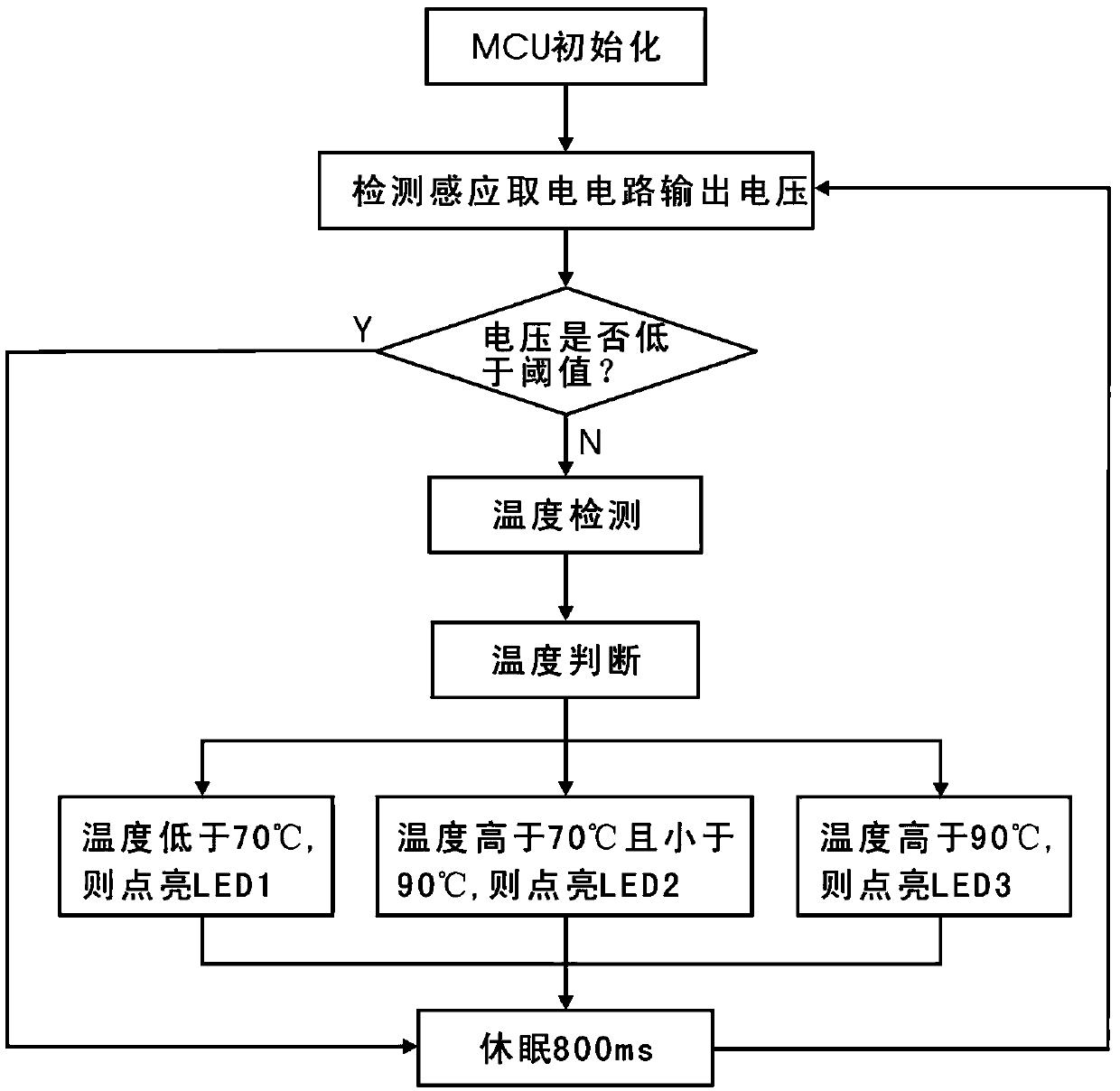
The invention discloses a micro-current induction power supply temperature measuring and alarming device and a temperature measuring and alarming method. The micro-current induction power supply temperature measuring and alarming device comprises an inductive electricity taking circuit and a temperature measuring and alarming circuit, wherein the inductive electricity taking circuit provides a power supply for the temperature measuring and alarming circuit; the inductive electricity taking circuit comprises a current inductor, a rectification filter circuit, a voltage stabilizing circuit, a voltage monitoring chip and a three-terminal switch, the current inductor is composed of an unclosed magnetic core and a coil which winds the unclosed magnetic core, the power supply output from the coil is controlled to output through the three-terminal switch after being rectified, filtered and stabilized, and the on / off of the three-terminal switch is controlled through the voltage monitoring chip. The micro-current induction power supply temperature measuring and alarming device automatically goes to sleep at definite time or under low voltage, so that the electric energy consumption is lowered, and the effective micro-power consumption work is realized. The temperature measuring and alarming device has advantages of convenience in mounting, small volume, low cost and high reliability, is applicable to various small spaces on site, and prompts the user to pay attention to the temperature abnormity of the equipment through different colors of light so that the user is convenient to observe in long distance.

Description

Technical field [0001] The invention relates to a temperature measurement alarm device, in particular to a micro-current induction power supply type temperature measurement alarm device and a temperature measurement alarm method applied to electrical equipment. Background technique [0002] The live display and temperature measurement devices are mainly used in the electric power industry, mainly to monitor the temperature conditions of the connection points of various electrical equipment indoors and outdoors, and realize the functions of live display and temperature exceeding alarm. [0003] Power equipment has been operating under high-voltage and high-current conditions for a long time, so the electrical connection points are likely to burn the equipment due to the high temperature of the electrical connection points due to poor contact, and even the short circuit failure of the equipment due to the high temperature, the expansion of the accident, and the serious damage to the e...

Claims


Application Information

Patent Timeline
IPC IPC(8): H02J17/00G08B5/36H02J50/00
Inventor 黄新宇李家建薛晔
Owner 四川瑞霆智汇科技有限公司
Learn More