
Control circuit of charge pump and charge pump circuit

A technology of control circuit and charge pump, applied in the direction of conversion equipment without intermediate conversion to AC, to achieve the effect of reducing the number of operations, reducing power consumption, and prolonging time

Inactive Publication Date: 2014-05-21
SHANGHAI HUAHONG GRACE SEMICON MFG CORP
View PDF5 Cites 11 Cited by
  • Summary
  • Abstract
  • Description
  • Claims
  • Application Information

AI Technical Summary

Problems solved by technology

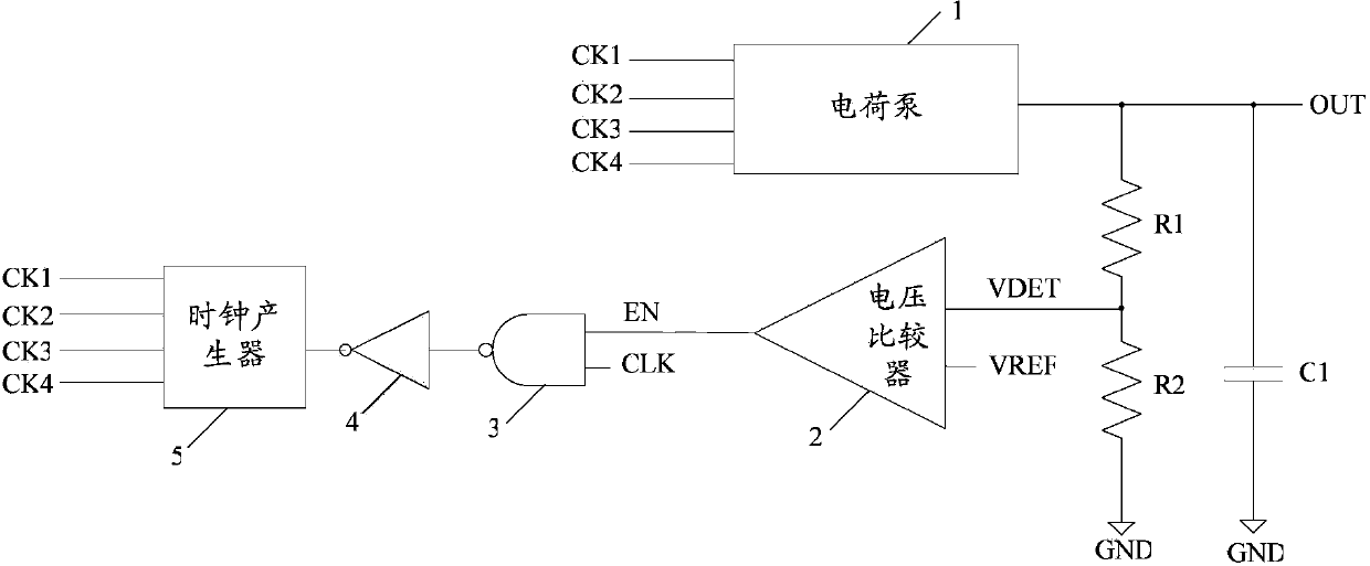
[0012] In the voltage adjustment stage, the sampling voltage VDET is continuously compared with the reference voltage VREF to generate the enable signal EN, and the charge pump 1 will switch frequently under the action of the enable signal EN to maintain the output voltage of the charge pump at the target value. However, the constant frequency band switching of the charge pump will generate a lot of power consumption

Method used


Image

  • Control circuit of charge pump and charge pump circuit
  • Control circuit of charge pump and charge pump circuit
  • Control circuit of charge pump and charge pump circuit

Examples


Embodiment Construction

[0033] In order to make the above objects, features and advantages of the present invention more comprehensible, specific embodiments of the present invention will be described in detail below in conjunction with the accompanying drawings.

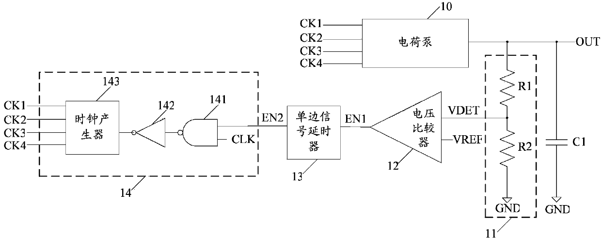
[0034] like image 3 As shown, the embodiment of the present invention provides a control circuit of the charge pump 10 . The control circuit includes: a sampling circuit 11 , a voltage comparator 12 , a single-side signal delayer 13 and a clock control signal obtaining circuit 14 .

[0035] The sampling circuit 11 is adapted to sample the output voltage of the charge pump 10 to obtain a sampling voltage VDET. The first input terminal of the voltage comparator 12 is suitable for inputting the sampling voltage VDET, the second input terminal of the voltage comparator 12 is suitable for inputting the reference voltage VREF, and the output terminal of the voltage comparator 12 is suitable for outputting the first enable signal EN1 . The si...


PUM


Abstract

The invention discloses a control circuit of a charge pump and a charge pump circuit. The control circuit of the charge pump comprises a sampling circuit, a voltage comparator, a single-side signal delayer and a clock control signal acquisition circuit, wherein the sampling circuit is suitable for sampling the output voltage of the charge pump to obtain sampling voltage; the first input end of the voltage comparator is suitable for inputting the sampling voltage, the second input end of the voltage comparator is suitable for inputting reference voltage, and the output end of the voltage comparator is suitable for outputting a first enabling signal; the single-side signal delayer is suitable for delaying the falling edge of the first enabling signal to obtain a second enabling signal; the clock control signal acquisition circuit is suitable for outputting a clock control signal to the charge pump when the second enabling signal is at a high level.

Description

technical field [0001] The invention relates to a charge pump control circuit and a charge pump circuit. Background technique [0002] A charge pump circuit is a circuit that uses the accumulation of charges in a capacitor to generate a high voltage, and it is widely used in memory circuits. [0003] figure 1 It is a structural schematic diagram of an existing charge pump circuit, and the charge pump circuit includes: a charge pump 1, a first resistor R1, a second resistor R2, a voltage comparator 2, a NAND gate circuit 3, an inverter 4, a clock generator 5 and load capacitor C1. [0004] The output terminal OUT of the charge pump 1 is connected to the first terminal of the first resistor R1 and the first terminal of the load capacitor. The charge pump 1 may be a four-phase charge pump. [0005] The second terminal of the first resistor R1 is connected to the first terminal of the second resistor R2 and the first input terminal of the voltage comparator. The second end ...

Claims


Application Information

Patent Timeline
Patent Type & Authority Applications(China)
IPC IPC(8): H02M3/07
Inventor 张圣波杨光军胡剑
Owner SHANGHAI HUAHONG GRACE SEMICON MFG CORP
Learn More