A method of orienting carbon nanotubes by means of motion

A technology for orienting carbon nanotubes and carbon nanotubes, which is applied in nanotechnology, nanotechnology, nanostructure manufacturing, etc., can solve problems such as complex operations, high electric field strength, and increased difficulty in the orientation of carbon nanotubes, achieving a high degree of orientation , The effect of simple operation of orientation

Active Publication Date: 2016-03-02
NO 53 RES INST OF CHINA NORTH IND GRP
View PDF5 Cites 0 Cited by
  • Summary
  • Abstract
  • Description
  • Claims
  • Application Information

AI Technical Summary

Problems solved by technology

[0003]Application No. 200710018343.0 Chinese Patent Application Publication Discloses a combination of carbon nanotube physical field formed by magnetic field or electrostatic field and laminar flow field in the polymer The method of aligning and aligning the carbon nanotubes in this method is carried out in the polymer, which undoubtedly increases the difficulty of the orientation of the carbon nanotubes. Therefore, it is necessary to use a complex combination of physical fields to carry out the orientation alignment, and the operation is relatively complicated.
[0004] Chinese Invention Patent Publication with application number 201210206835.3 discloses a method for aligning carbon nanotubes. The carbon nanotubes are oriented in the electric field before being implanted into the base layer. The orientation of the carbon nanotubes in this method is completely dependent on the electric field, so the required electric field strength is relatively large

Method used


Image

  • A method of orienting carbon nanotubes by means of motion
  • A method of orienting carbon nanotubes by means of motion
  • A method of orienting carbon nanotubes by means of motion

Examples


Embodiment 1

[0024] Place a 75cm×500cm unidirectional glass fiber cloth soaked in epoxy resin on the workbench, and its width direction is the glass fiber direction.

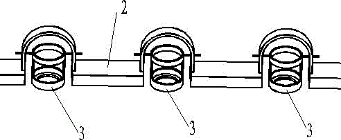
[0025] An iron support 2 is set above the surface of the glass fiber cloth, which consists of three U-shaped structures and four horizontal plates, such as figure 1 As shown, by means of welding or riveting, the four horizontal plates are fixedly connected to the three U-shaped structures respectively. Among them, the length of the two middle horizontal plates is 20cm, and the length of the two horizontal plates at both ends is 15cm. The distance between the two horizontal plates is 5 cm, and holes with a diameter of 0.3 cm are opened on both sides of the U-shaped structure. The fixture 3 of the ultrasonic spray head is fixed on its upper end, a cylinder with a diameter of 0.25cm and a length of 1cm, which is rotatably connected with the U-shaped structure. The upper part of the fixture 3 is a circle with a height of 8cm, an...

Embodiment 2

[0030] Place a 170cm×520cm copper plate on the workbench, place a 150cm×500cm unidirectional glass fiber cloth impregnated with phenolic resin in the center above the copper plate, and its width direction is the direction of the glass fiber.

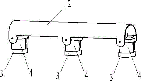
[0031] Iron support 2 is set above the glass fiber cloth surface, such as figure 2 As shown, it is a U-shaped structure with a length of 120 cm and a distance of 4.8 cm between the two side wings. On the side wings along the length direction of the support 2, a hole with a diameter of 0.3 cm is opened every 50 cm.

[0032] The structure of the fixing device 3 of the ultrasonic spray head is the same as that of the first embodiment, and is connected to the bracket 2 in a rotatable manner by fixing a cylinder with a diameter of 0.25 cm and a length of 1 cm fixed on its upper end.

[0033] The ZPQ-S-95 ultrasonic spray head is placed upside down in the fixing device 3. When it is vertically downward, the outlet position of the spray head i...

Embodiment 3

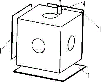
[0038] Such as image 3 As shown, a 30cm×30cm×30cm cube prepreg is placed on the worktable, and there are holes with a diameter of 5cm on the top surface and the center of the two sides, and 10cm×10cm are respectively placed on the outside 2cm of the surface with holes. copper plate.

[0039] The DPQ-T-95 ultrasonic spray head is installed on the M-10iAe spraying robot, and the storage tank connected with the spray head contains single-walled carbon nanotubes with an outer diameter of 3 nm and a length of 12 μm uniformly dispersed in chloroform. The weight content is 0.1%.

[0040] Connect the positive pole of the power supply with a voltage of 1.2 kV to the spray head, and the negative pole to the bottom copper plate, set the flow rate of the metering liquid pump to 2ml / min, start the metering liquid pump, and turn on the air pump, and set its pressure to 0.1MPa. Then start the robot, make the spray head take the hole center of the top face as the center, and make a circula...


PUM


Abstract

The invention discloses a method and a device for orientating a carbon nano tube by means of moving. Due to quick relative motion between a carbon nano tube releasing device and a matrix with viscous fluid on the surface, when two ends of a carbon nano tube fall onto the matrix surface not at the same time, the end falls onto the matrix surface firstly is resisted by friction of the viscous fluid on the matrix surface, and the other end falling later continuously moves forwards along a direction of the relative motion under the action of an inertia force and covers the matrix surface along an expected direction finally. To achieve a better effect, an electric field can be applied in the moving process of the carbon nano tube, so that the carbon nano tube can be orientated along the direction of the electric field during falling, and orientating effect of the carbon nano tube on the matrix is improved obviously. In addition, the method has the advantages of simplicity in operation and quick implementation in large scale, and the device has the advantages of simple structure, low investment and convenience in use.

Description

technical field [0001] The invention relates to a material orientation method, in particular to a carbon nanotube orientation method. Background technique [0002] Carbon nanotubes are seamless, hollow tubes formed by graphene sheets formed by carbon atoms. Since their discovery by Iijima in 1991, they have attracted widespread attention for their unique structures and excellent properties. Studies have shown that carbon nanotubes have a theoretically high strength of 200GPa and a superhigh modulus of more than 1TPa. Their theoretical tensile strength is 100 times that of steel, and their density is only 1 / 7 to 1 / 6 of steel. Carbon nanotubes are considered to be one of the most potential reinforcement phase materials for advanced resin-based composite materials. In addition, carbon nanotubes also have excellent thermal, electrical, magnetic, and dielectric properties. Therefore, if carbon nanotubes are used according to Arranged in a certain direction on the substrate in an...

Claims


Application Information

Patent Timeline
Patent Type & Authority Patents(China)
IPC IPC(8): B82B3/00B82Y40/00
Inventor 陈以蔚秦贞明王丹勇魏化震郑志才徐井利李树虎郭建芬
Owner NO 53 RES INST OF CHINA NORTH IND GRP
Why Eureka
Try Eureka