Check patentability & draft patents in minutes with Patsnap Eureka AI!

Three-dimensional array imaging measurement method of dielectric resistivity around wellbore

A dielectric resistance, three-dimensional array technology, used in earth-moving drilling, wellbore/well components, etc., can solve the problems of shallow detection range, poor focusing effect, and insufficient longitudinal resolution, so as to improve longitudinal resolution and deepen lateral detection. Depth, shortened length effects

Active Publication Date: 2016-04-20
CHINA UNIV OF PETROLEUM (EAST CHINA)
View PDF5 Cites 0 Cited by
  • Summary
  • Abstract
  • Description
  • Claims
  • Application Information

AI Technical Summary

Problems solved by technology

Some traditional logging tools are increasingly unable to meet the requirements of logging analysis, especially for the detailed description and quantitative orientation of deviated wells, highly deviated wells, horizontal wells, thin beds, heterogeneous formations, non-induced fractures and caves Interpret flushing zone, invasion zone, undisturbed formation resistivity, judge invasion zone radius, flushing zone radius, etc.
[0003] The original array lateral instrument uses hardware focusing, and the circuit realizes the main monitoring control through a closed loop, which is greatly affected by the external environment (such as temperature changes, power fluctuations, etc.), and the residual voltage between the hardware focusing monitoring electrodes cannot be eliminated, and the focusing effect is poor. Moreover, due to the influence of surrounding rock, the vertical resolution is not high enough, and at the same time, it cannot provide heterogeneity information around the well
Micro-resistivity scanning tools and peripheral scanning imaging can conduct directional analysis of the medium around the wellbore, but the detection range is very shallow, and there is no ability to distinguish the induced fractures and holes induced during the drilling process from the original formation fractures and holes

Method used


Image

  • Three-dimensional array imaging measurement method of dielectric resistivity around wellbore
  • Three-dimensional array imaging measurement method of dielectric resistivity around wellbore
  • Three-dimensional array imaging measurement method of dielectric resistivity around wellbore

Examples


Embodiment Construction

[0033] In order to facilitate a further understanding of the method and the achieved effects of the present invention, preferred embodiments are described in detail below in conjunction with the accompanying drawings.

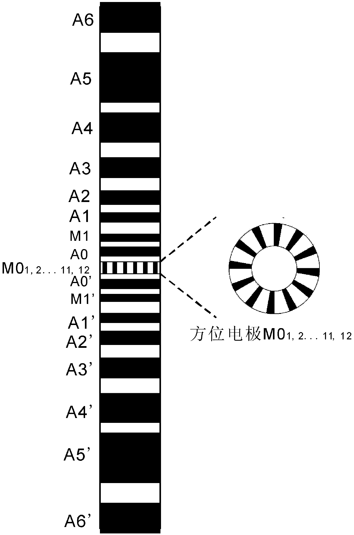
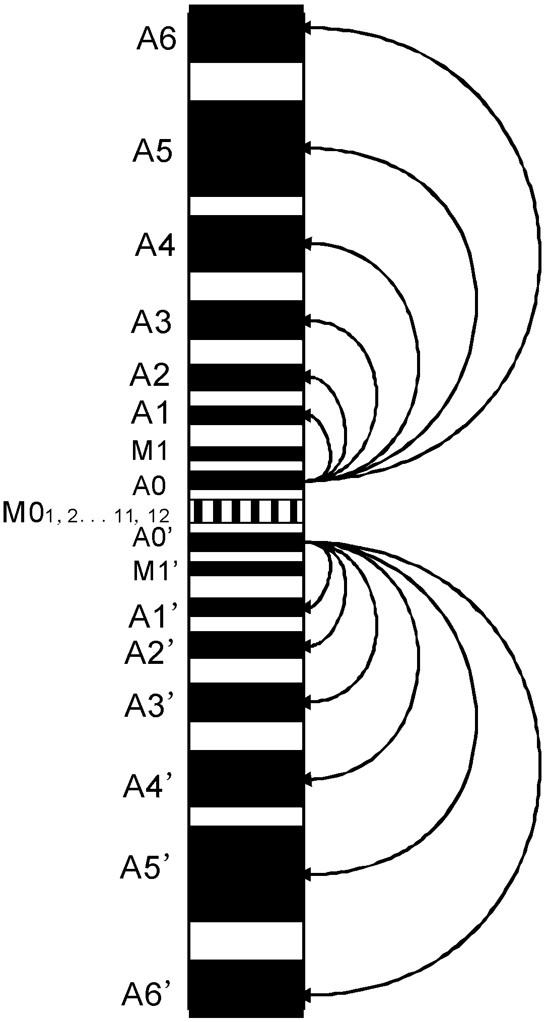
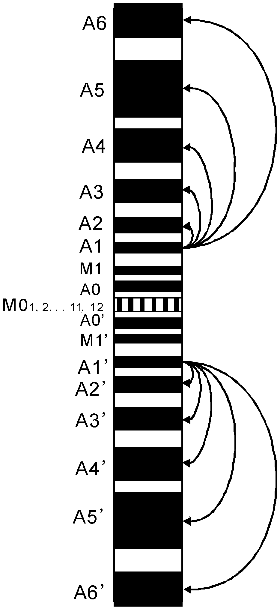
[0034] combine Figure 12 and Figure 1 to Figure 7 The three-dimensional array imaging measurement method of the surrounding medium resistivity of the present invention is described. In the present invention, a long cylindrical detector is first put into the well, and the detector is provided with an array azimuth electrode system, such as figure 1 As shown, the array azimuth electrode system is composed of symmetrically distributed lateral electrode rings embedded on an insulating carrier and an azimuth electrode ring located in the center of the detector. The array azimuth electrode is composed of a mandrel, a metal electrode and a fiberglass insulator or a rubber rod insulator. The azimuth electrode ring M0 located in the center of the instrument is comp...


PUM


Abstract

The invention discloses a three-dimensional array imaging measurement method for the resistivity of a well surrounding medium. The method comprises the following steps: I, placing a detector into a well, wherein the detector is provided with an array direction electrode system, the array direction electrode system comprises a plurality of electrodes and works in a plurality of different working modes, each working mode corresponds to one type of electric field distribution, and signals are transmitted at different working frequencies in each working mode; II, calculating a plurality of array lateral curves; III, calculating a plurality of direction lateral curves; IV, imaging the direction lateral curves to obtain a well surrounding 360-degree numerical simulation imaging pattern; V, analyzing the resistivity of heterogeneity stratums in different directions around a well through the array lateral curves, the direction lateral curves and the well surrounding imaging pattern, evaluating inclined wells, highly-deviated wells, horizontal wells, thin layers, heterogeneity stratums, non-induced fractures and holes, quantitatively explaining the resistivity of flushed zones, invasion zones and undisturbed formations, and judging the radiuses of the invasion zones and the flushed zones.

Description

technical field [0001] The invention relates to an array azimuth lateral logging method, in particular to a three-dimensional array imaging measurement method for medium resistivity around a well and an array azimuth electrode system for realizing the method. Background technique [0002] With the needs of oilfield exploration and development, the accuracy of reservoir evaluation is getting higher and higher, and logging instruments are also developing continuously. Some traditional logging tools are increasingly unable to meet the requirements of logging analysis, especially for the detailed description and quantitative orientation of deviated wells, highly deviated wells, horizontal wells, thin beds, heterogeneous formations, non-induced fractures and caves Interpret flushing zone, invasion zone, undisturbed formation resistivity, judge invasion zone radius, flushing zone radius, etc. [0003] The original array lateral instrument uses hardware focusing, and the circuit r...

Claims


Application Information

Patent Timeline
Patent Type & Authority Patents(China)
IPC IPC(8): E21B49/00
Inventor 邓少贵李栗李智强范宜仁何绪全
Owner CHINA UNIV OF PETROLEUM (EAST CHINA)
Features
  • R&D
  • Intellectual Property
  • Life Sciences
  • Materials
  • Tech Scout
  • Unparalleled Data Quality
  • Higher Quality Content
  • 60% Fewer Hallucinations
Learn More