Variable-pressure and variable-working-condition oil burning nozzle

A technology of changing working conditions and oxidants, which is applied in the direction of burners, lighting and heating equipment, etc., can solve the problems of poor safety of on-site operators, restrictions on high-pressure coal gasification technology, and long processing time for flameout accidents, so as to shorten the processing time, The effect of shortening the ignition time and improving the adaptability to load changes

Active Publication Date: 2014-05-28
CHANGZHENG ENG
View PDF8 Cites 13 Cited by
  • Summary
  • Abstract
  • Description
  • Claims
  • Application Information

AI Technical Summary

Problems solved by technology

[0004] When the coal-water slurry gasifier is started, the start-up burner is under the condition of slight negative pressure and normal pressure. When the temperature in the furnace reaches the feeding temperature, the start-up burner is removed, and the refractory brick and the start-up burner blind flange are installed at the same time. The gasifier can only be fed and started, and the ignition method is manual ignition. Therefore, the entire start-up and ignition process is cumbersome to operate, low in automation, easy to turn off and difficult to detect, labor-intensive for workers, and poor safety for on-site operators
[0005] When the pulverized coal pressurized gasifier is started, the start-up burner can realize variable pressure and variable working condition load adjustment within a certain pr

Method used


Image

  • Variable-pressure and variable-working-condition oil burning nozzle
  • Variable-pressure and variable-working-condition oil burning nozzle
  • Variable-pressure and variable-working-condition oil burning nozzle

Examples


Embodiment Construction

[0040] The present invention will be described below in conjunction with the accompanying drawings of the present invention.

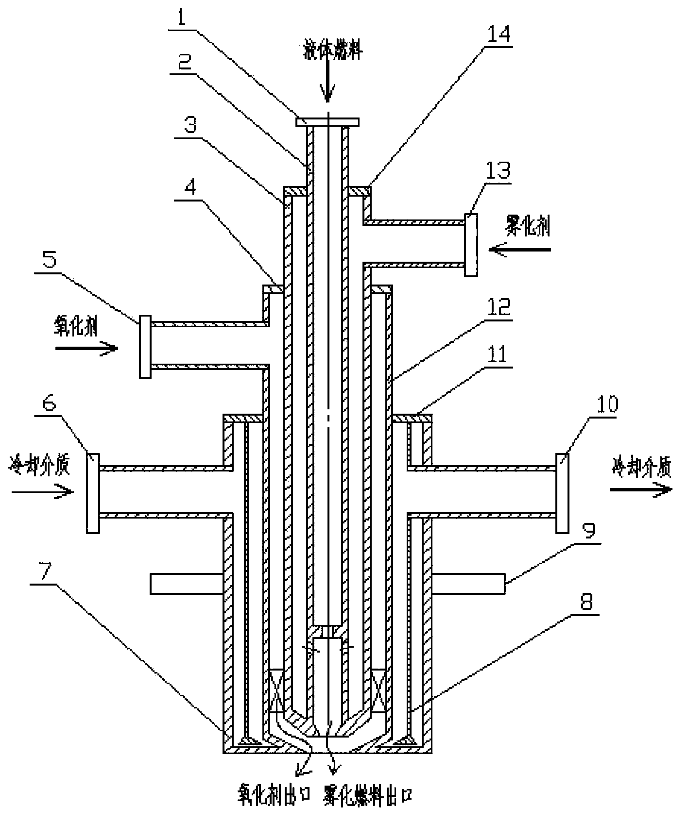
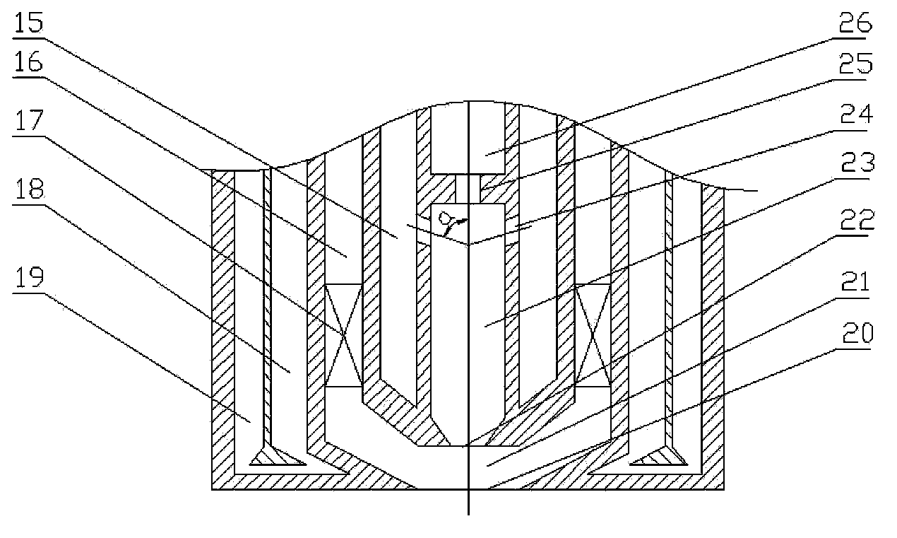
[0041] see figure 1 and figure 2 , an oil burner with variable pressure and variable working conditions according to the present invention, including a burner body sleeve and a premixed jet head. The outermost layer of the body and head of the burner is provided with a cooling structure, and is sealed and connected with the gasifier body (not shown in the figure) through the installation flange 9 .

[0042]The body sleeves are coaxially arranged, and from the inside to the outside are the liquid fuel outer sleeve 2, the atomizing agent outer sleeve 3, and the oxidizer outer sleeve 12. The annular space between the casing and the casing forms various medium passages, wherein the passage formed by the innermost liquid fuel outer casing 2 itself is the liquid fuel passage 26, and the gap between the liquid fuel outer casing 2 and the atomizing agent ou...


PUM


Abstract

The invention provides a variable-pressure and variable-working-condition oil burning nozzle. The variable-pressure and variable-working-condition oil burning nozzle is a technical burning nozzle which is adapt to high-pressure environments, applicable to coal gasifiers, provided with igniting and burning capabilities in an operation process with random fixed pressure, variable pressure and continuous variable working conditions in a pressure range of 0-2.0MPaG, and used for igniting the coal gasifiers. The burning nozzle comprises body sleeves and a premix jet flow head. The body sleeves are in coaxial arrangement and include a liquid fuel outer sleeve, an atomizing agent outer sleeve and an oxidizing agent outer sleeve sequentially from inside to outside, and an annular space between each two sleeves form a medium passage. The premix jet flow head comprises inner and outer contraction type sonic or subsonic nozzles and two-level atomizing and mixing chambers and capable of realizing efficient atomizing and mixing of fuels and oxidizing agents and stable ignition and combustion. A double-layer closed annular passage cooling structure is arranged on the outermost layers of the head and the body of the burning nozzle, the burning nozzle is hermetically connected with a coal gasifier body through a mounting flange, and tightness and ablation avoidance of the burning nozzle under the furnace pressure of 0-8MPaG and at the furnace temperature of 1200-1700DEG C can be guaranteed.

Description

technical field [0001] The invention relates to an oil burner, in particular to a new type of start-up burner which is used in a gasification furnace and can adapt to variable pressure and variable working conditions in a high-pressure environment. Background technique [0002] Efficient and clean coal gasification technology is the mainstream of coal gasification technology development in my country today. The industrialized coal gasification technology mainly includes pulverized coal pressurization and coal-water slurry gasification. [0003] The gasifier is the key equipment for coal-water slurry gasification and pulverized coal pressurized gasification technology, and the start-up process of the gasifier is usually completed by the start-up burner. [0004] When the coal-water slurry gasifier is started, the start-up burner is under the condition of slight negative pressure and normal pressure. When the temperature in the furnace reaches the feeding temperature, the star...

Claims


Application Information

Patent Timeline
IPC IPC(8): F23D11/10F23D11/38
Inventor 王明坤姜从斌信伟郭进军陈拴柱魏佳
Owner CHANGZHENG ENG
Why Eureka
Try Eureka