
Optical fiber Bragg optical grating low-temperature sensor for simultaneously measuring strain and temperature and application method thereof

A technology of sensors and temperature-measuring optical fibers, which is applied in the field of low-temperature strain and temperature sensors of optical fiber Bragg gratings, and can solve problems such as lack of effective packaging protection

Active Publication Date: 2014-05-28
YUN NAN ELECTRIC TEST & RES INST GRP CO LTD ELECTRIC INST +2
View PDF8 Cites 7 Cited by
  • Summary
  • Abstract
  • Description
  • Claims
  • Application Information

AI Technical Summary

Problems solved by technology

The substrate-encapsulated fiber Bragg grating strain sensor uses a polyimide film polymer substrate to package the bare fiber Bragg grating. Since there is no temperature compensation grating inside the sensor, an additional fiber Bragg grating temperature sensor needs to be connected in series to achieve temperature compensation; the thin stainless steel tube The packaged optical fiber Bragg grating low temperature sensor only uses a thin stainless steel tube with a large thermal expansion coefficient to encapsulate the bare optical fiber Bragg grating, and its exterior lacks effective packaging protection against external forces.

Method used


Image

  • Optical fiber Bragg optical grating low-temperature sensor for simultaneously measuring strain and temperature and application method thereof
  • Optical fiber Bragg optical grating low-temperature sensor for simultaneously measuring strain and temperature and application method thereof
  • Optical fiber Bragg optical grating low-temperature sensor for simultaneously measuring strain and temperature and application method thereof

Examples


Embodiment Construction

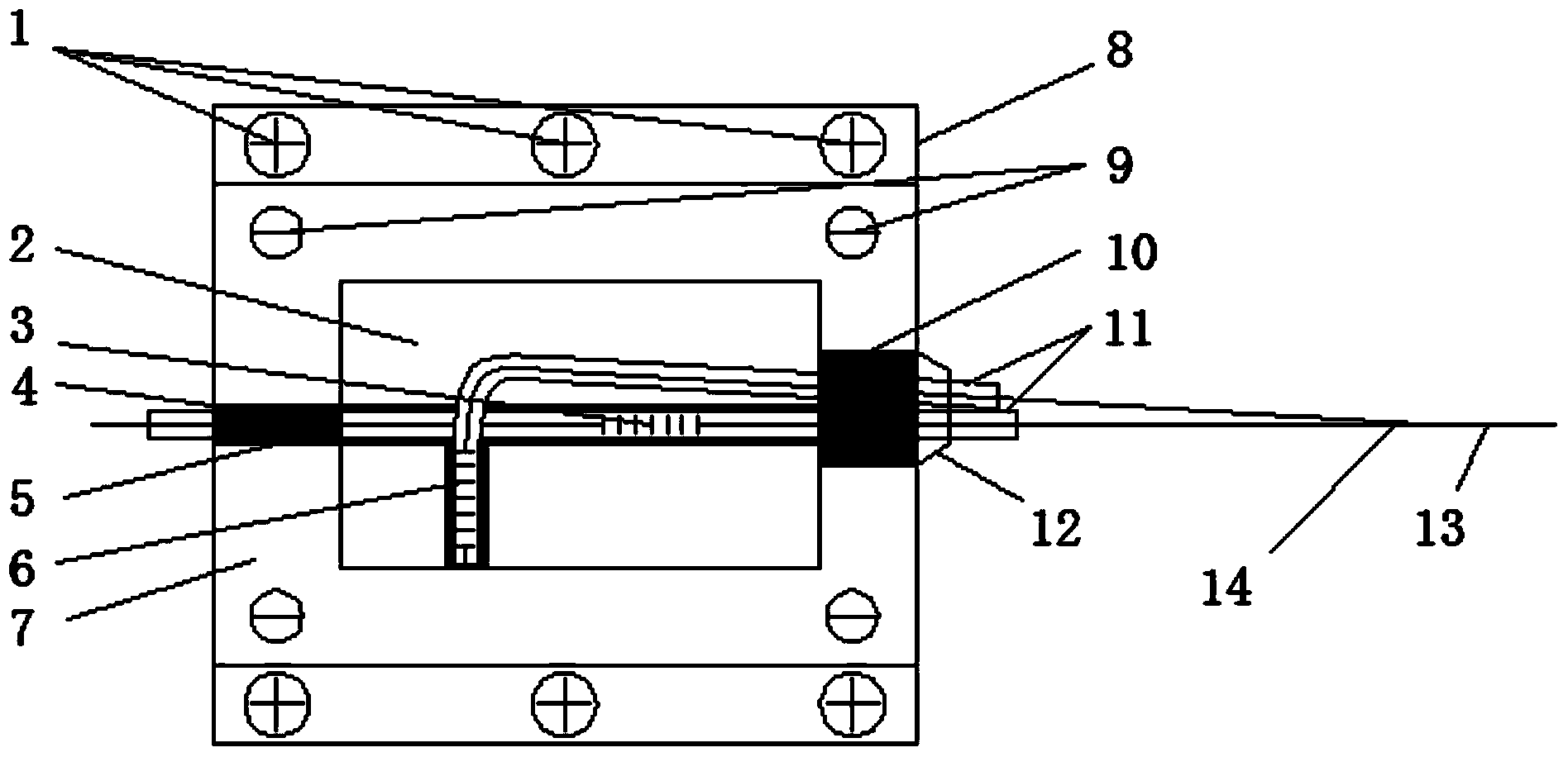
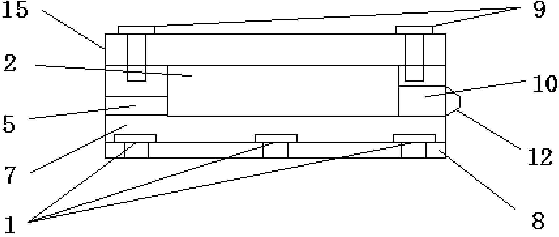
[0038] see Figure 1~2, the top cover 15 and the copper shell 7 are connected by the top cover screw 9 to form the measurement cavity 2, the copper shell 7 is fixed on the measured object by the fixed base 8 and the base fixing screw 1, the strain fiber Bragg grating 3 and the temperature measuring fiber Bragg The grating 6 is packaged with a thin copper tube 11 and a low-temperature adhesive 4, the strained fiber Bragg grating 3 is pasted along the axis direction of the bottom of the copper shell 7 with a low-temperature adhesive 4, and the temperature-measuring fiber Bragg grating 6 is glued along the vertical axis of the bottom of the copper shell 7 with a low-temperature adhesive 4 Direction paste, one end of the strained fiber Bragg grating 3 is led out through the upper fiber outlet hole 5, and fixed to the copper shell 7 with a low-temperature adhesive 4, and the other end and the temperature-measuring fiber Bragg grating 6 are led out through the lower fiber outlet hole...


PUM


Abstract

The invention provides an optical fiber Bragg optical grating low-temperature sensor for simultaneously measuring strain and temperature and an application method of the optical fiber Bragg optical grating low-temperature sensor. The optical fiber Bragg optical grating low-temperature sensor comprises a base fixing screw (1), a measuring cavity (2), a strain optical fiber Bragg optical grating (3), a low-temperature adhesive (4), an upper-end optical fiber leading-out hole (5), a temperature-measuring optical fiber Bragg optical grating (6), a copper shell (7), a fixed base (8), a top cover screw (9), a lower-end optical fiber leading-out hole (10), a thin copper pipe (11), a fastening sleeve (12), an input / output optical fiber (13), an optical fiber continuing point (14) and a top end cover (15). The optical fiber Bragg optical grating low-temperature sensor for simultaneously measuring the strain and the temperature can be used for carrying out online monitoring on the strain and the temperature under the low-temperature environment of 77K-273K by the measurement on the wavelength displacement of the optical fiber Bragg optical grating.

Description

technical field [0001] The invention relates to an optical fiber Bragg grating low-temperature strain and temperature sensor for simultaneously measuring low-temperature strain and temperature and a use method thereof, belonging to the technical field of optoelectronic measurement. Background technique [0002] The superconducting magnetic energy storage device uses a superconducting coil as an energy storage coil, which is excited by the power grid through the converter, and stores the electric energy in the form of electromagnetic energy of LI2 / 2 in the coil magnetic field. When necessary, the electromagnetic energy is transferred by the inverter A new type of energy storage device that converts AC power back to the grid or provides it to other loads. The high-temperature superconducting magnetic energy storage device is mainly composed of superconducting magnets, cryogenic containers, cooling devices, current conversion devices and measurement and control systems. It work...

Claims


Application Information

Patent Timeline
IPC IPC(8): G01D21/02
Inventor 王达达李晓龙李川张少泉宋萌李英娜
Owner YUN NAN ELECTRIC TEST & RES INST GRP CO LTD ELECTRIC INST
Learn More