Flow cell battery system used for off-grid solar power generation system

A power generation system and flow battery technology, which is applied in the direction of fuel cells, photovoltaic power generation, fuel cell additives, etc., can solve the problems of poor operation, low efficiency, and high power consumption of the flow battery system. Achieve the effect of reducing energy storage costs, increasing revenue, and extending power supply time

Active Publication Date: 2014-05-28
DALIAN RONGKE POWER
View PDF7 Cites 4 Cited by
  • Summary
  • Abstract
  • Description
  • Claims
  • Application Information

AI Technical Summary

Problems solved by technology

[0004] Due to the advantages of good charge and discharge performance, large capacity, long life, and high safety, flow batteries are increasingly used in solar photovoltaic power generation systems instead of conventional batteries. When flow batteries are applied to off-grid solar power generation systems, In order to meet the charging power of the photovoltaic array, the power of the liquid flow battery system is generally close to the rated power of the photovoltaic array. The liquid flow battery system includes stacks, electrolyte storage tanks, and other auxiliary equipment such as circulation pumps and liquid delivery pipelines. It is configured according to the charging power. In this way, in the discharge mode, due to the relatively low load power, the internal power consumption of the flow battery system is extremely large and the efficiency is very low, and the operation effect of the entire flow battery system is not good.

Method used


Image

  • Flow cell battery system used for off-grid solar power generation system
  • Flow cell battery system used for off-grid solar power generation system
  • Flow cell battery system used for off-grid solar power generation system

Examples


Embodiment Construction

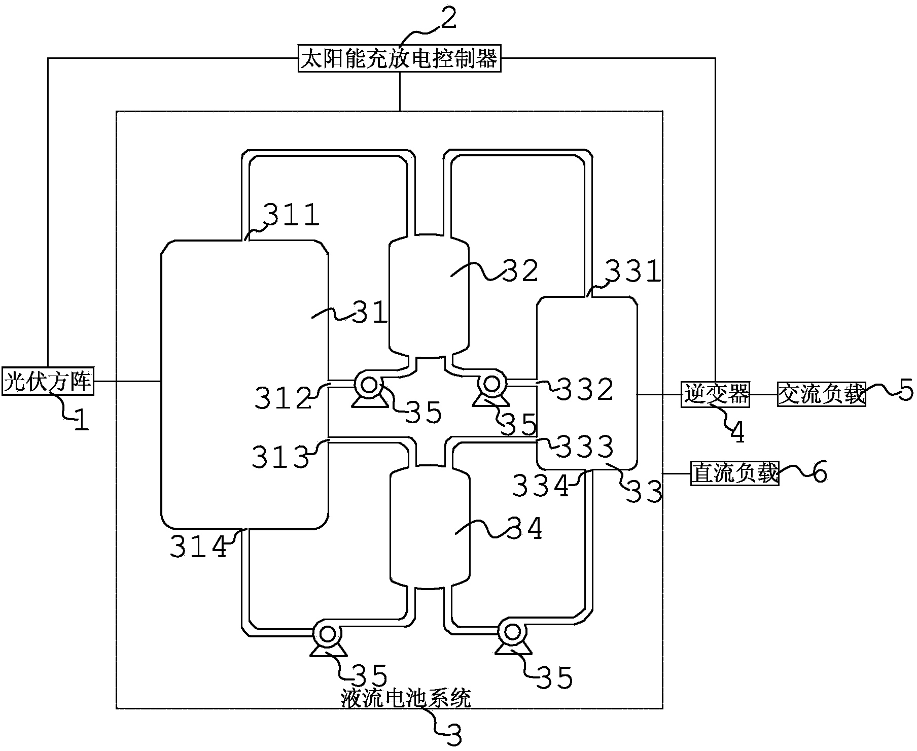
[0022] Such as figure 1 A liquid flow battery system for an off-grid solar power generation system is shown, the off-grid solar power generation system includes a photovoltaic array 1, a solar charge and discharge controller 2, an inverter 4, a DC load 6 and an AC The load 5, the liquid flow battery system 3 includes: a first stack unit 31 connected to the photovoltaic array 1 and the solar charge and discharge controller 2; connected to the DC load 6 and the solar charge and discharge controller 2, and through The inverter 4 is connected to the second stack unit 33 of the AC load 5; the positive liquid storage tank 32; the negative liquid storage tank 34; the positive electrolyte outlet 311 of the first stack unit, and the positive electrolyte outlet of the second stack unit 331 are respectively connected to the positive electrode liquid storage tank 32 through the liquid delivery pipeline; the negative electrode electrolyte solution outlet 313 of the first stack unit and the...


PUM


Abstract

The invention discloses a flow cell battery system used for an off-grid solar power generation system. The flow cell battery system comprises a first electricity accumulating unit which is connected with a photovoltaic square matrix and a solar power charging and discharging controller, a second electricity accumulating unit which is connected with a direct current load and the solar power charging and discharging controller and is connected with an alternate current load through an inverter, an anode liquid storage tank, and a cathode liquid storage tank, wherein the anode electrolyte outlet of the first electricity accumulating unit and the anode electrolyte outlet of the second electricity accumulating unit are connected with the anode liquid storage tank; the cathode electrolyte outlet of the first electricity accumulating unit and the cathode electrolyte outlet of the second electricity accumulating unit are connected with the cathode liquid storage tank; the anode liquid storage tank is connected with the anode electrolyte inlet of the first electricity accumulating tank and the anode electrolyte inlet of the second electricity accumulating tank; the cathode liquid storage tank is connected with the cathode electrolyte inlet of the first electricity accumulating unit and the cathode electrolyte inlet of the second electricity accumulating unit. The flow cell battery system is lower in energy consumption during the discharging process.

Description

technical field [0001] The invention relates to a liquid flow battery system, in particular to a liquid flow battery system used in an off-grid solar power generation system. Background technique [0002] Off-grid solar power generation systems are widely used in remote mountainous areas, areas without electricity, islands, communication base stations, etc., which generally include photovoltaic arrays composed of solar cell components, solar charge and discharge controllers, battery packs, and inverters. , DC load and AC load; the photovoltaic array converts solar energy into electrical energy when there is light, and controls the photovoltaic array to supply power to the DC load and charge the battery pack through the solar charge and discharge controller; when there is no light, the solar charge and discharge control The inverter controls the battery pack to supply power to the DC load, and the inverter converts the DC output from the photovoltaic array or the battery pack...

Claims


Application Information

Patent Timeline
Patent Type & Authority Applications(China)
IPC IPC(8): H01M8/18H01M8/04H02S40/38H02J7/00H01M8/04298
CPCH01M8/04283H01M8/188H02J7/00Y02E10/50Y02E60/50Y02E70/30
Inventor 张宇张华民杨振坤马相坤王晓丽李颖
Owner DALIAN RONGKE POWER
Why Eureka
Try Eureka