

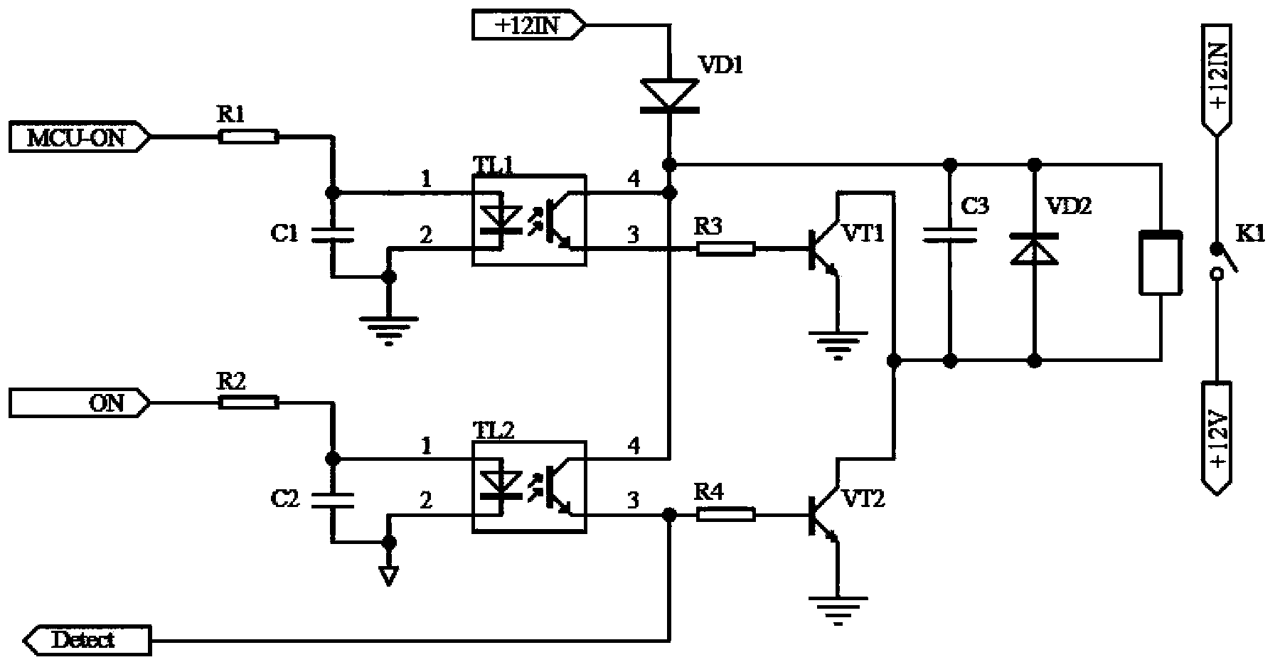
Dormancy control circuit
A control circuit and drive circuit technology, applied in electric traction, electric vehicles, vehicle energy storage, etc., to achieve the effect of reducing battery power consumption
- Summary
- Abstract
- Description
- Claims
- Application Information
AI Technical Summary
Problems solved by technology
Method used
Image

Examples
Embodiment Construction
[0018] In order to further explain the technical means and effects of the present invention to achieve the intended purpose of the invention, the specific implementation, structure, characteristics and effects of the dormancy control circuit proposed according to the present invention will be described below in conjunction with the accompanying drawings and preferred embodiments. The details are as follows.
[0019] The working principle of the dormancy control circuit of the present invention is: when the electric vehicle is in the off state, the connection between the battery management system and the power supply is disconnected, and the battery management system is in the dormant state; when the electric vehicle is started, the key switch of the electric vehicle The control signal ON output by the circuit controls the conduction of one optocoupler, and the drive circuit drives the relay to pull in, the battery management system is powered on, and the battery management syst...
PUM
 Abstract
Description
Claims
Application Information