
A high pile cap foundation structure

A technology for foundation structures and high pile caps, applied in foundation structure engineering, water conservancy projects, artificial islands, etc., can solve problems such as lack of cable routing, personnel work and rest space, lack of operation and maintenance, and damage to foundation structures, etc., to achieve convenient operation Maintenance and work and rest, improve overall rigidity and strength, and prevent corrosion

Inactive Publication Date: 2016-04-27
哈电风能(福建)有限公司
View PDF5 Cites 0 Cited by
  • Summary
  • Abstract
  • Description
  • Claims
  • Application Information

AI Technical Summary

Problems solved by technology

[0004] The patent number is 201220297967.7, and the utility model patent titled "A High Pile Cap Foundation for an Offshore Wind Farm" discloses a high pile cap foundation for an offshore wind farm, including a cap and multiple piles, each pile The upper end of each pile is embedded in the cap, and the part of each pile embedded in the cap is fixed with a reinforcing ring. The utility model effectively solves the problem that cracks are easily generated on the contact surface between the foundation pile and the concrete of the existing high pile cap in the offshore wind farm. leading to problems with compromised infrastructure
[0005] Although the existing high-pile cap foundation structure has its own advantages, it lacks auxiliary equipment and devices such as operation and maintenance and berthing as a whole, and lacks functions such as cable routing and personnel work and rest space.

Method used


Image

  • A high pile cap foundation structure

Examples


Embodiment 1

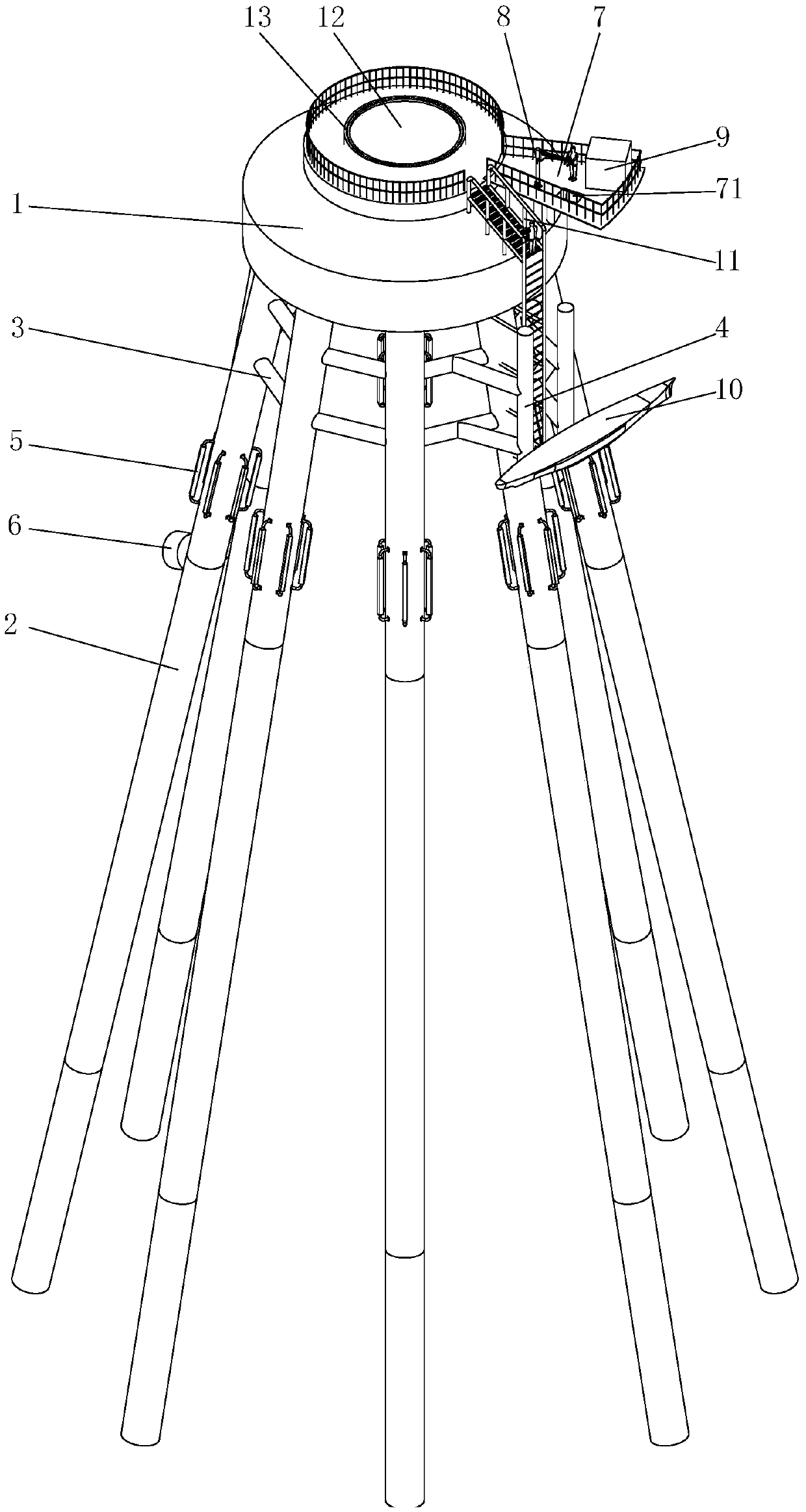
[0037] When the high pile cap foundation structure of the present invention is in use, the operation and maintenance ship 10 is docked beside the anti-collision bar 4, and the operation and maintenance personnel board the maintenance platform 12 from the ladder 11; then the operation and maintenance personnel pass the material through the material hole through the crane 8 71 is lifted from the operation and maintenance ship 10 to the platform 7 or cap 1, and the material hole 71 realizes the lifting of the equipment between the platform 7 and the operation and maintenance ship 10; when the container 9 is an electrical container, the safety distance and maintenance space between the electrical equipment are sufficient , which is convenient for the operation and maintenance personnel to operate. When the container 9 is a temporary rest container, it is convenient for the operation and maintenance personnel to rest; when the fan cable needs to be routed, the cable can pass through ...

Embodiment 2

[0039] In this embodiment, two containers 9 can be set on the platform 1, one of which is an electrical container and the other is a temporary rest container, which is convenient for installation of electrical equipment and for personnel to rest.


PUM


Abstract

The invention discloses a high pile cap foundation structure, which comprises a concrete cap higher than sea level, and a group of steel pipe piles arranged at the bottom of the concrete cap for supporting the cap, and the upper part of the steel pipe pile is embedded in the bottom of the cap , the group of steel pipe piles is distributed at the bottom of the cap in a frustum-cone shape, and a climbing ladder for climbing up the cap is provided on one side of the cap. There are anti-collision poles, anode active metals and wiring pipes are arranged on the steel pipe pile, an outwardly extending platform is arranged on the cap platform, and a crane and more than one container are arranged on the cap platform or the platform. In the high pile cap foundation structure of the present invention, since connecting rods are arranged between adjacent steel pipe piles, the overall rigidity and strength of the high pile cap foundation structure can be improved, and the anti-collision rods arranged on the connecting rods can prevent The operation and maintenance ship directly hits the steel pipe pile; the setting of the platform expands the usable area on the cap; containers and cranes can be set on the platform to facilitate the operation, maintenance and work of technicians.

Description

technical field [0001] The invention relates to offshore wind farm foundations, in particular to a high pile cap foundation for offshore wind farms. Background technique [0002] At present, most of the development of offshore wind farms is concentrated in Denmark, Germany, the Netherlands, the United Kingdom, Sweden, Ireland and other countries in Europe. The foundation forms are dominated by single pile foundations, accounting for 74%, followed by jacket foundations, and other foundations such as gravity foundations, tripod foundations, suction foundations, portal foundations, negative pressure foundations, and floating foundations are relatively more widely used. few. It started relatively late in China, and the offshore wind turbine foundation platform was developed from the offshore oil production platform in the oil and gas industry. One of its applications is the foundation of high pile caps. [0003] The patent number is 200920198988.1, and the utility model patent...

Claims


Application Information

Patent Timeline
Patent Type & Authority Patents(China)
IPC IPC(8): E02D27/42E02D27/44E02D27/52E02D27/14
CPCE02B17/003E02B17/0034
Inventor 刘胜祥谭文理肖华林林金瑞杨琼
Owner 哈电风能(福建)有限公司
Learn More