
Ventilation control system for tunnel face

A ventilation control system and tunnel ventilation technology, applied in mine/tunnel ventilation, comprehensive factory control, comprehensive factory control, etc., can solve problems such as difficulty in obtaining optimal control, differences in the working status of ventilation equipment, and being taken out of the outside of the tunnel, etc. Achieve the effect of high practical value, simple structure and low input cost

Inactive Publication Date: 2014-06-04
XIAN ZHONGZHI HUIZE PHOTOELECTRIC TECH
View PDF0 Cites 10 Cited by
  • Summary
  • Abstract
  • Description
  • Claims
  • Application Information

AI Technical Summary

Problems solved by technology

Nowadays, after the ventilation equipment used in tunnel construction is laid out and the parameters are set, it is generally not adjusted accordingly. However, due to various emergencies in the actual construction process, the air quality at the tunnel face will be affected to varying degrees , and there will be differences in the working status of the ventilation equipment
In addition, dust and other particles in the air cannot be completely taken out of the tunnel with the dirty air. Therefore, it is difficult to optimally control the air quality at the face of the tunnel if it is close to the existing ventilation device.
To sum up, there is a lack of a tunnel face ventilation control system with reasonable design, convenient layout and installation, easy operation, high intelligence, and good use effect, which can monitor the results of the air conditions at the face, Corresponding optimal control of the environmental conditions at the face of the operation

Method used


Image

  • Ventilation control system for tunnel face

Examples


Embodiment Construction

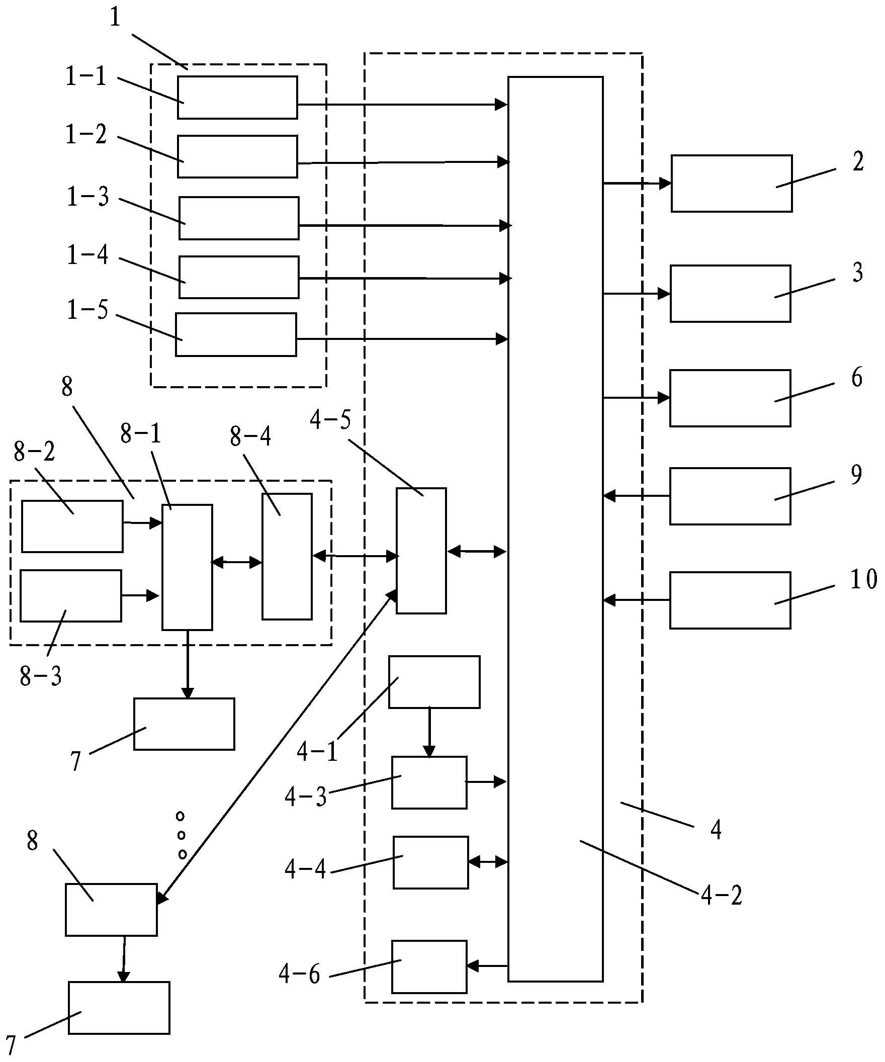
[0027] Such as figure 1 As shown, the present invention includes a control device 4 arranged at the face of the constructed tunnel, a tunnel ventilation device arranged in the constructed tunnel, and an air quality condition for real-time detection of the air quality at the face of the constructed tunnel. The monitoring device 1 and the oxygen-generating equipment 2 and the liquid dedusting and spraying equipment 3 arranged at the face of the tunnel under construction. The tunnel ventilation device includes multiple groups arranged in the tunnel hole under construction from front to back along the excavation direction of the tunnel under construction. And the air supply device that continuously sends the fresh air outside the cave into the tunnel surface and the exhaust fan 6 arranged at the tunnel surface and discharges the dirty air from the tunnel to the outside of the tunnel, and the multiple sets of the air supply devices include A blower fan 7 and the ventilation duct co...


PUM


Abstract

The invention discloses a ventilation control system for a tunnel face. The ventilation control system comprises a control device, a tunnel ventilation device, an air quality status monitoring device, an oxygen generating plant and a liquid dust-removal spray device, wherein the control device is arranged on the tunnel face of a construction tunnel, the tunnel ventilation device is arranged in the construction tunnel, the air quality status monitoring device is used for monitoring the air quality status of the tunnel face of the construction tunnel in real time, and the oxygen generating plant and the liquid dust-removal spray device are distributed on the tunnel face of the construction tunnel. The tunnel ventilation device comprises multiple sets of air supply devices and an exhaust fan arranged on the tunnel face. The control device comprises a control keyboard, a monitor, a keyboard circuit, a data storage unit and a second wireless communication module, wherein the keyboard circuit is connected with the control keyboard, and the data storage unit and the second wireless communication module are connected with the monitor respectively. The oxygen generating plant, the liquid dust-removal spray device and the exhaust fan are all controlled by the monitor and are connected with the monitor respectively. The ventilation control system is reasonable in design, convenient to install and lay, easy and convenient to use and operate, good in use effect, and capable of optimally regulating and controlling environmental conditions of the tunnel face.

Description

technical field [0001] The invention relates to a control system, in particular to a ventilation control system for tunnel faces. Background technique [0002] The function of ventilation in tunnel construction is to deliver enough fresh air from the outside of the tunnel to the inside of the tunnel, and discharge the gun smoke and harmful gases produced by blasting and transportation in the tunnel, so as to finally ensure the needs of the workers and machinery in the tunnel for fresh air, so that the inside of the tunnel The air meets the standards stipulated by the country and the industry. The quality of the ventilation effect in the construction of long tunnels directly affects the progress of the project and the health of the workers. At present, the tunnel construction ventilation at home and abroad mostly adopts the pipeline press-in ventilation method, and an axial flow fan is installed outside the tunnel entrance. The dirty air in the tunnel will be discharged out...

Claims


Application Information

Patent Timeline
IPC IPC(8): E21F1/00G05B19/418F04D27/00
CPCY02P90/02
Inventor 侯鹏
Owner XIAN ZHONGZHI HUIZE PHOTOELECTRIC TECH
Learn More