Single-pot electric energy storage device and using method thereof

An energy storage device and electric energy technology, applied in heat storage heaters, fluid heaters, lighting and heating equipment, etc., can solve the problems of reduced average utilization time of electric equipment, unrealizable upgrade methods, high cost of upgrade and expansion, and achieve The effect of wide working temperature range, improved power utilization efficiency and simple structure

Active Publication Date: 2014-06-04
中投亿星新能源投资有限公司
View PDF4 Cites 9 Cited by
  • Summary
  • Abstract
  • Description
  • Claims
  • Application Information

AI Technical Summary

Problems solved by technology

Such upgrades and expansions are costly, especially in congested urban areas, where traditional upgrade methods cannot even be realized, such as no road corridors, or the inability to lay lines due to environmental and aesthetic considerations, etc.
Therefore, it is becoming more and more difficult for the installed capacity of the device to meet the demand of the peak load, which leads to the power grid being cut off during the peak load, and many units have to be shut down when the load is low. The frequent start and stop of the unit not only increases energy consumption, but also affects the life of the unit. Reduce the average utilization time of power equipment, reduce power generation efficiency, and reduce economic benefits

Method used


Image

  • Single-pot electric energy storage device and using method thereof
  • Single-pot electric energy storage device and using method thereof
  • Single-pot electric energy storage device and using method thereof

Examples


Embodiment 1

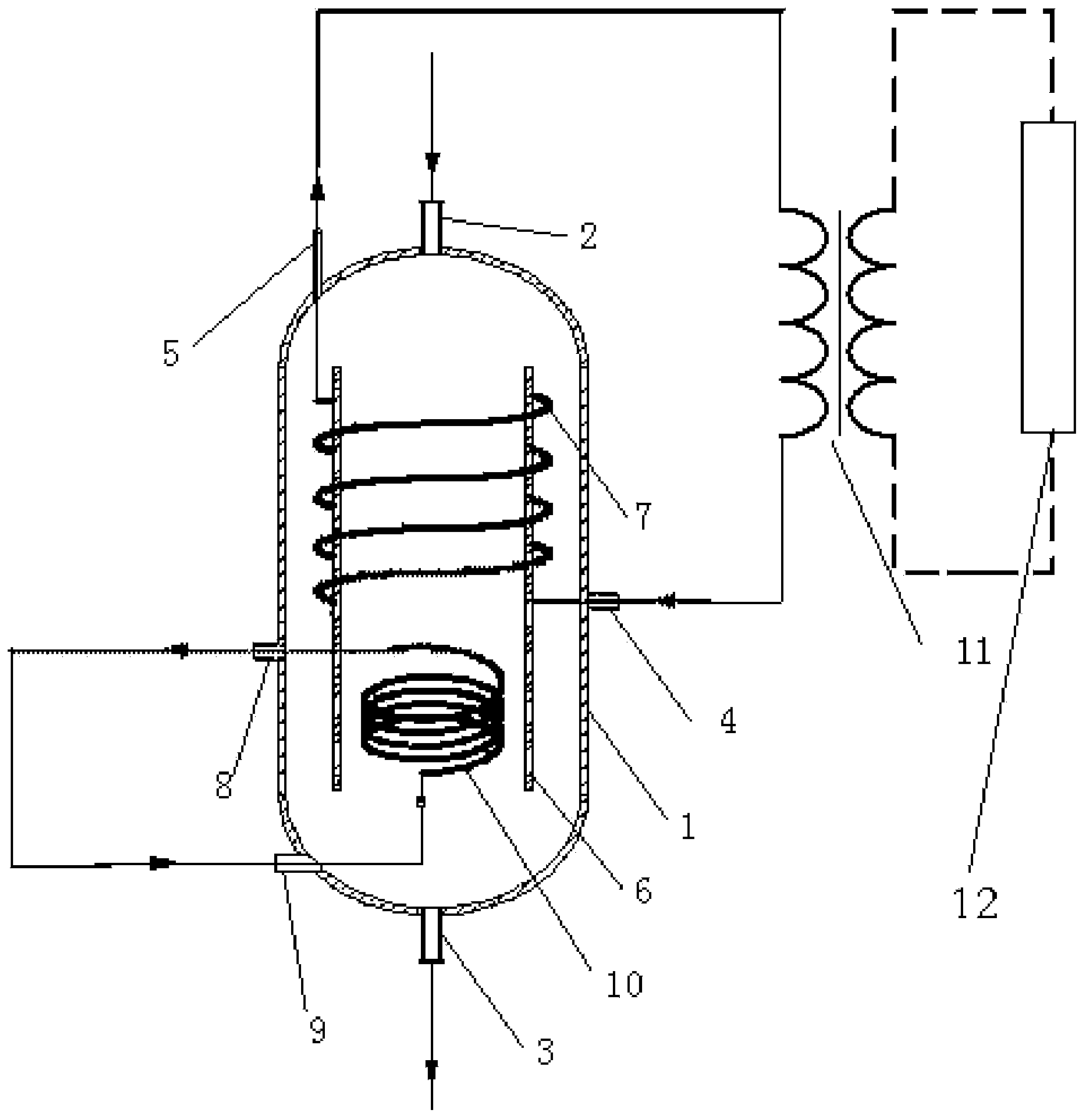
[0032] Such as figure 1 The single-tank energy storage device shown includes an energy storage tank body 1, a heat storage medium inlet 2, a heat storage medium outlet 3, an energy release medium inlet 4, an energy release medium outlet 5, an electric heater 10, and an electric heater connection 口, energy utilization device 12;

[0033] The heat storage medium inlet 2 is provided at the top of the energy storage tank body 1; the heat storage medium outlet 3 is provided at the bottom of the energy storage tank body 1;

[0034] The energy release medium inlet 4, the energy release medium outlet 5, and the electric heater connection port are provided on the energy storage tank body 1, wherein the energy release medium inlet 4 is below the energy release medium outlet 5;

[0035] The electric heater 10 is arranged at the bottom of the energy storage tank body 1. If the electric heater 10 is a spiral tube heater, the electric heater connection port includes the electric heater power inlet ...

Embodiment 2

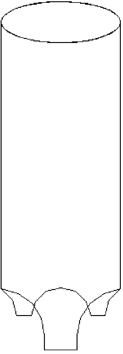
[0041] Similar to Embodiment 1, except that the electric heater is changed to a cylindrical heater, and the connection port is the power inlet 9 of the electric heater. image 3 Shown.

Embodiment 3

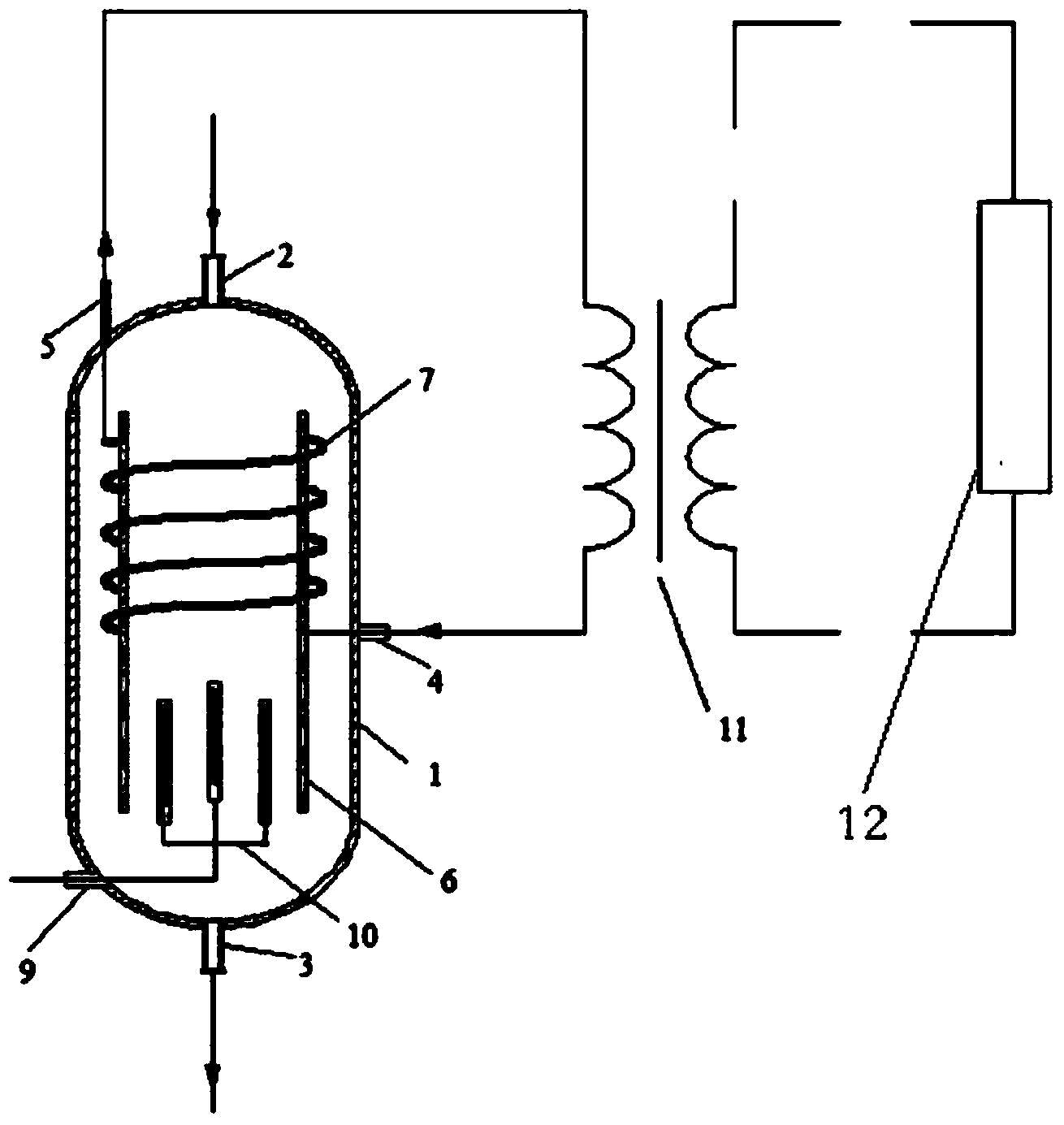
[0043] Such as Figure 4 As shown, it is similar to Embodiment 2, except that the energy utilization device 12 is changed to a conventional heating / hot water supply device, and the energy utilization heat exchanger 11 is removed. The other processes are the same as in Embodiment 2. Using water as the energy release medium, water enters the energy release heat exchanger 7 in the energy storage tank from the energy release medium inlet 4, and the temperature rises and pressure increases, and it exits from the energy release medium outlet 5 and enters conventional heating / heating The water installation realizes the effective use of heat energy.


PUM


Abstract

The invention relates to a single-pot electric energy storage device which comprises an energy storage pot body, a heat storage medium inlet, a heat storage medium outlet, an energy releasing medium inlet, an energy releasing medium outlet, an electric heater, an electric heater connector and an energy utilization device. The energy storage medium inlet is formed in the top of the energy storage pot body, and the heat storage medium outlet is formed in the bottom of the energy storage pot body. The energy releasing medium inlet, the energy releasing medium outlet and the electric heater connector are formed in the energy storage pot body, wherein the energy releasing medium inlet is located below the energy releasing medium outlet. The electric heater is arranged on the bottom inside the energy storage pot body, and the energy utilization device is connected between the energy releasing medium inlet and the energy releasing medium outlet in series. According to the single-pot electric energy storage device, on the one hand, the utilization efficiency of wind power and photovoltaic power generation is improved; on the other hand, the peak and valley problem of a power grid is solved, the problem that urban pollution is serious is solved, and the electric energy utilization efficiency of wind power and solar photovoltaic power generation and the power grid is improved.

Description

Technical field [0001] The invention relates to the technical field of effective utilization of wind power / photovoltaic power generation and grid valley electricity, and in particular to a single-tank energy storage device for wind power / photovoltaic power generation and grid valley electricity and a use method thereof. Background technique [0002] Smog has enveloped China, energy shortage and environmental pollution have become unprecedented challenges facing my country, and the development of renewable energy is a strategic national policy of my country. In July 2012, my country issued the "Twelfth Five-Year Development Plan for Renewable Energy". By 2015, my country's grid-connected wind power and solar capacity will reach 100 million kw and 15 million kw, respectively; by 2020, wind and solar grid-connected installed capacity Reached 200 million kw and 50 million kw respectively. However, the inherent intermittency and volatility of renewable energy such as wind and solar en...

Claims


Application Information

Patent Timeline
Patent Type & Authority Applications(China)
IPC IPC(8): F24H7/02
Inventor 鹿院卫吴玉庭杜文彬孙晓丽李小丽马重芳
Owner 中投亿星新能源投资有限公司
Why Eureka
Try Eureka