Submatrix level linear constraint self-adaptive beam forming method based on feature subspaces

An adaptive beam and characteristic subspace technology, applied in radio wave measurement systems, instruments, etc., can solve problems such as signal processing influence, weight vector not satisfying constraint conditions, and side lobe elevation

Active Publication Date: 2014-06-04
BEIJING INSTITUTE OF TECHNOLOGYGY
View PDF0 Cites 17 Cited by
  • Summary
  • Abstract
  • Description
  • Claims
  • Application Information

AI Technical Summary

Problems solved by technology

When the LCMV algorithm is directly applied to the sub-array level, it will cause the main lobe of the adaptive pattern to be deformed and the side lobes to increase, which will have a negative impact on subsequent signal processing (target angle measurement, target detection, etc.)
At this time, in order to keep the shape of the main lobe and reduce the side lobe, it is not possible to directly multiply the window function on the static weight vector of LCMV, because the weight vector obtained in this way does not satisfy the original constraints

Method used


Image

  • Submatrix level linear constraint self-adaptive beam forming method based on feature subspaces
  • Submatrix level linear constraint self-adaptive beam forming method based on feature subspaces
  • Submatrix level linear constraint self-adaptive beam forming method based on feature subspaces

Examples


Embodiment 1

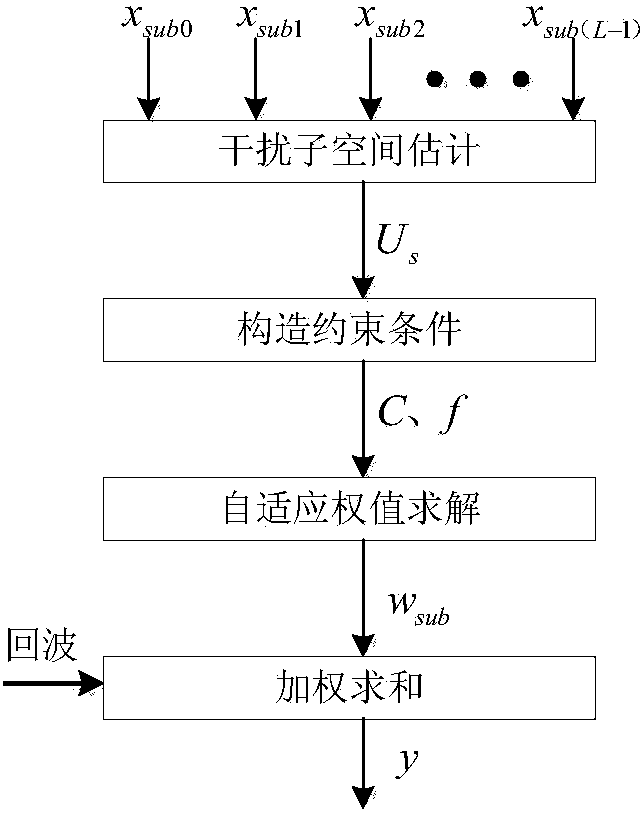
[0045] Based on the above basic scheme, the method for calculating the subarray-level covariance matrix of the receiving array in step 1 is:

[0046] First establish the signal model: for a linear array with N array elements, d n is the distance between the n-th array element of the linear array and the reference point, where n takes all positive integers between 0 and N-1, and the reference point is the arbitrarily selected i-th array element, usually the 0th array element Yuan is the reference point, at this time d 0 =0; For a linear array, when there are P mutually uncorrelated interference signals, the receiving array is X(t)=AS(t)+N(t), where L≥P.

[0047] where A=[a(θ P ),…a(θ 1 )], S(t)=[s 1 (t),...,s P (t)] T , a(θ P )~a(θ 1 ) is in turn a linear array relative to P interfering signal steering vectors, where θ p is the incident direction of the pth interference signal, and the value of p is between 1 and P; a ( ...

Embodiment 2

[0052] In this embodiment, on the basis of the above-mentioned embodiment 1, assuming that the direction of the desired signal is consistent with the beam direction of the array antenna, the method of calculating the subarray-level covariance matrix in step 1 is: according to the side lobe level of the receiving array pattern, The phase shift value and the sub-array transfer matrix are obtained, and the sub-array level covariance matrix is ​​obtained according to the sub-transfer matrix and the covariance matrix of the receiving array.

[0053] Wherein the sub-array transfer matrix is ​​specifically: T=W win ΦT 0 , where W win is the diagonal matrix of weighting coefficients, W win =diag(w n ) n=0,1,… , N-1 , diag(·) is a diagonal matrix formed by ·, where w n is the weighting coefficient of the nth array element, determined according to the side lobe level of the receiving array pattern, where n takes all integers between 0 and N-1; Φ is a diagonal array of phase shift ...

Embodiment 3

[0060] After step 1, the estimated interference subspace is obtained. In order to obtain the adaptive weight vector, it is necessary to construct a constraint matrix and a constraint response vector, so that the algorithm can adaptively suppress the interference signal and keep the beam pointing at θ 0 The gain of is a constant, the sub-array-level constraint matrix constructed in step 2 of this embodiment is C, and the corresponding vector of sub-array-level constraints is f:

[0061] C=[a sub (θ 0 ), U s ]=[a sub (θ 0 ),e 1 ,e 2 ,...,e P ]; f = [μ,0,0,...,0] 1×(P+1) ;

[0062] a sub (θ 0 ) is the steering vector of the desired signal at the subarray level;

[0063] μ is a constant, specifically, in the desired signal direction θ 0 The array gain at , usually takes a value of 1.

[0064] The sub-array-level constraint matrix C and the corresponding vector f of the sub-array-level constraints satisfy: w sub H C=f, where w sub is the adaptive weight vector.

[...


PUM


Abstract

The invention discloses a submatrix level linear constraint self-adaptive beam forming method based on feature subspaces, and belongs to the technical field of array signal processing. The method includes the steps that eigenvalue decomposition is conducted on a sampling covariance matrix, so that the needed interference subspaces are estimated, then, interference signals are restrained in a self-adaptive mode by the way that interference subspace constraint beam response is zero, a self-adaptive directional diagram is constrained by introducing a penalty function, so that a main lobe achieves shape preserving, and a side lobe is lowered. According to the method, self-adaptive interference restraint is carried out, meanwhile main lobe shape preserving and side lobe lowering of the self-adaptive directional diagram obtained in a submatrix are achieved, and good output SINR performance can be obtained. The method is suitable for submatrix level linear constraint self-adaptive beam forming.

Description

technical field [0001] The invention belongs to the technical field of array signal processing, and relates to an improved subarray-level linear constraint adaptive beamforming method based on a characteristic subspace. Background technique [0002] Adaptive digital beamforming (ADBF) technology makes full use of the spatial information obtained by the array antenna. By sampling the spatial signal field and then obtaining the desired output results through weighting processing, it is convenient to perform beam control and effectively suppress spatial interference and Therefore, it is widely used in many military and national economic fields such as radar, communication, sonar, navigation, voice signal processing, earthquake monitoring and biomedical engineering. For such a wide application of adaptive beamforming technology, its application quality generally depends on the computing speed and robustness of the adaptive beamforming algorithm. After decades of development and...

Claims


Application Information

Patent Timeline
Patent Type & Authority Applications(China)
IPC IPC(8): G01S7/02G01S7/36
CPCG01S7/02G01S7/2813G01S7/36
Inventor 杨小鹏曾涛张宗傲胡晓娜
Owner BEIJING INSTITUTE OF TECHNOLOGYGY
Why Eureka
Try Eureka