
2-1T1R (2-1transistor1resistor) RRAM (resistive random access memory) unit with reading self-reference function

A technology of reference storage unit and storage unit, which is applied in read-only memory, information storage, static memory, etc., can solve the problems of reducing the success rate of reading, reducing the reading speed, and being unable to track the deviation of the resistive variable unit, so as to improve the Effect of read speed and success rate

Inactive Publication Date: 2014-06-04
SHANDONG SINOCHIP SEMICON
View PDF5 Cites 20 Cited by
  • Summary
  • Abstract
  • Description
  • Claims
  • Application Information

AI Technical Summary

Problems solved by technology

Therefore, it is difficult to provide an ideal reference current for current-mode-based reading circuits
First of all, it is impossible to use a fixed reference current, because it cannot track the high resistance state and low resistance state of the resistive variable unit due to the deviation caused by the region and temperature.
For the shared reference unit, although it is possible to track the change of resistance with the region and temperature, the resistance of the reference unit itself also has a consistency problem, which is a normal distribution. For high-resistance units or low-resistance units, the read margin cannot be guaranteed. degree is always (I L –I H ) / 2(I L is the current when the resistive variable unit is in a low resistance state, I H is the current when the resistive variable unit is in a high-resistance state), so it will not only reduce the reading speed, but also greatly reduce the reading success rate

Method used


Image

  • 2-1T1R (2-1transistor1resistor) RRAM (resistive random access memory) unit with reading self-reference function
  • 2-1T1R (2-1transistor1resistor) RRAM (resistive random access memory) unit with reading self-reference function
  • 2-1T1R (2-1transistor1resistor) RRAM (resistive random access memory) unit with reading self-reference function

Examples


Embodiment Construction

[0021] Embodiments of the present invention will be further described below in conjunction with the accompanying drawings and accompanying tables.

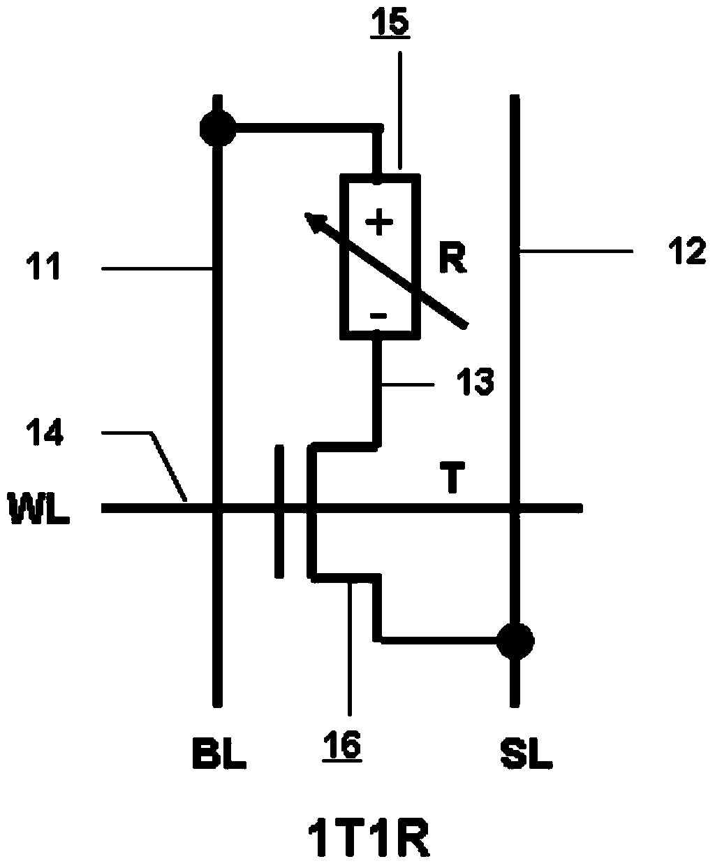
[0022] see figure 1 as shown, figure 1 It is a traditional 1T1R RRAM storage unit structure. Includes a resistive variable unit 15 and an NMOS select transistor 16 , 15 The anode is connected to the bit line 11, and the cathode is connected to the 16 The drain terminal 13 is connected, 16 The source terminal is connected to the source line 12 , and the gate terminal is connected to the word line 14 . when 15 When it is in a high-impedance state, 1T1R stores a value of '1', when 15 When it is in a low resistance state, 1T1R stores a value of '0'.

[0023] Please refer to Table 1, Table 1 shows the read and write operation conditions of the traditional 1T1R RRAM storage unit. When writing '1' to 1T1R, that is to 15 Perform set (set is the process of R changing from a high-impedance state to a low-impedance state), word li...


PUM


Abstract

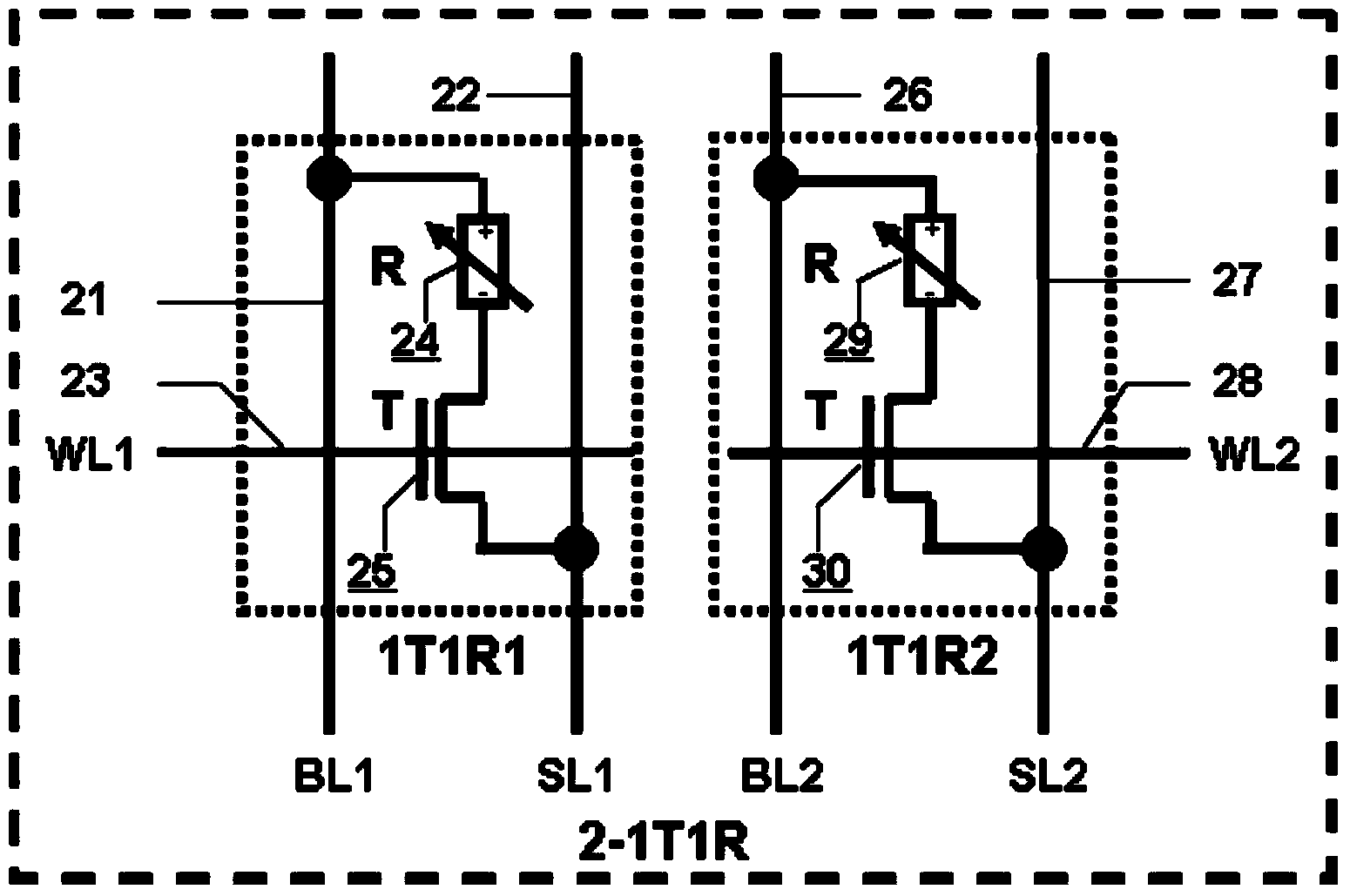
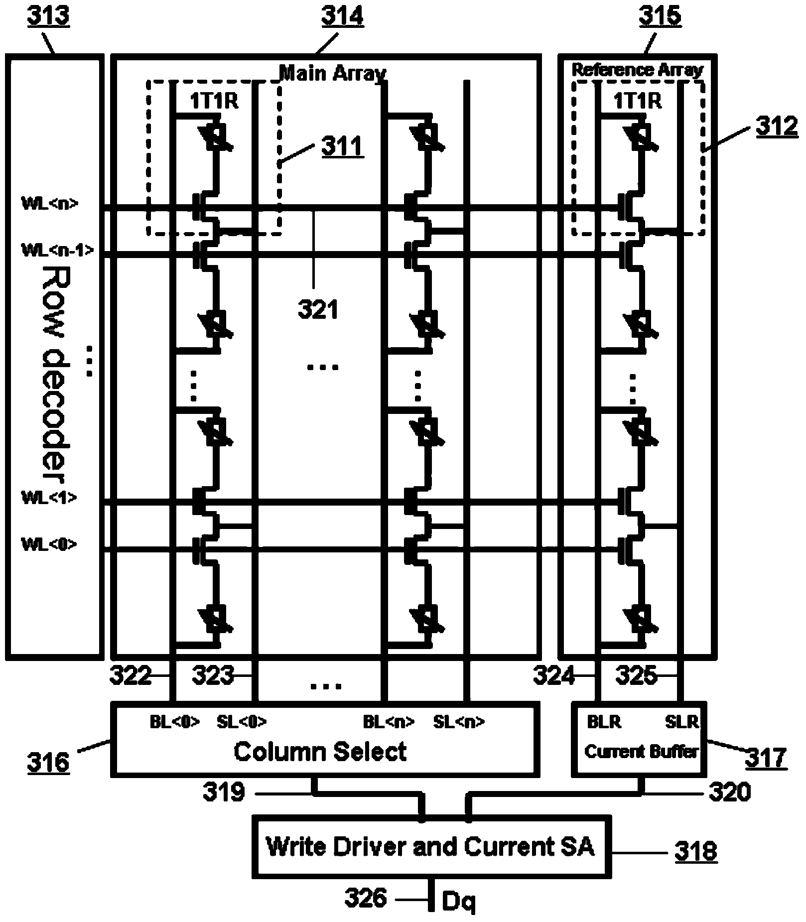
The invention provides a 2-1T1R (2-1transistor1resistor) RRAM (resistive random access memory) unit with a reading self-reference function. The 2-1T1R RRAM unit consists of two conventional RRAM 1T1R memory units, wherein one of the conventional RRAM 1T1R memory units is a main memory unit, and the other conventional RRAM 1T1R memory unit is a reference storage unit. During writing operation, the two 1T1R memory units are written as two opposite states respectively; if the main memory unit is written as '1' and the reference memory unit is written as '0', a 2-1T1R memory value is '1'; or if the main memory unit is written as '0' and the reference memory unit is written as '1', the 2-1T1R memory value is '0'. During reading operation, the reference memory unit serves as a reference unit for generating the reading reference current of the main memory unit. Compared with a conventional mode of using fixed reading reference current by a memory array or generating the reading reference current through a shared reference unit, the 2-1T1R RRAM unit has the advantages that the reading margin during the reading operation is doubled; the reading speed and the reading success rate are greatly improved.

Description

【Technical field】 [0001] The invention relates to the emerging field of non-volatile RAM design, in particular to a storage unit based on 1T1RRRAM. 【Background technique】 [0002] In recent years, driven by consumer markets such as smartphones, smart TVs, and tablet computers, flash memory has developed rapidly. However, due to complex mask patterns and expensive manufacturing costs, increasing word line leakage and crosstalk between cells, and fewer and fewer electrons in the floating gate, its ability to scale down has been greatly limited. It is estimated that the development to 1z nm will be difficult to continue to develop. Therefore, the emerging non-volatile memory CBRAM, MRAM, PRAM, RRAM, etc. are getting more and more attention. Among them, RRAM is considered to be the most powerful candidate for flash due to its high speed, large capacity, low power consumption, low cost and high reliability. [0003] However, due to the influence of process voltage and temperatu...

Claims


Application Information

Patent Timeline
IPC IPC(8): G11C16/06
CPCG11C7/04G11C13/004G11C2013/0042G11C2213/79G11C2213/82
Inventor 任奇伟潘立阳韩小炜
Owner SHANDONG SINOCHIP SEMICON
Learn More