Bleeding control module and silicon-controlled dimming LED drive circuit and system

A LED drive and control module technology, applied in energy-saving control technology, lamp circuit layout, light source, etc., can solve problems such as slow start-up process, abnormal work, temperature rise, etc., and achieve simple and effective compatibility, fast start-up, and improved The effect of startup speed

Active Publication Date: 2014-06-04
SHANGHAI BRIGHT POWER SEMICONDUCTOR CO LTD
View PDF4 Cites 24 Cited by
  • Summary
  • Abstract
  • Description
  • Claims
  • Application Information

AI Technical Summary

Problems solved by technology

[0004] 1) The discharge switch M2 has only two states of on and off, and the provided discharge current may be greater than the maintenance current demand of the thyristor dimmer 102, resulting in loss of LED drive circuit efficiency and high temperature rise; or less than the thyristor The maintenance current demand of the dimmer 102 causes the LED light to flicker or th

Method used


Image

  • Bleeding control module and silicon-controlled dimming LED drive circuit and system
  • Bleeding control module and silicon-controlled dimming LED drive circuit and system
  • Bleeding control module and silicon-controlled dimming LED drive circuit and system

Examples


Embodiment Construction

[0023] The thyristor dimming LED driving circuit and system provided by the present invention will be described in detail below in conjunction with the accompanying drawings.

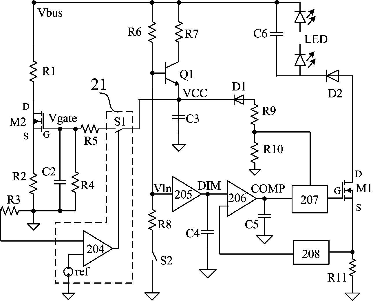
[0024] refer to figure 2 , a structural schematic diagram of the silicon controlled rectifier dimming LED drive circuit of the present invention, the drive circuit includes: a bleed switch MOS transistor M2, a first sampling resistor R3 and a bleed control module 21; the bleed The control module includes a comparator 204 , a reference voltage source ref and a first switch S1 .

[0025] The source S of the bleed switch MOS transistor M2 is electrically connected to the circuit ground through a resistor R2, its drain D is electrically connected to the bus voltage signal terminal (Vbus terminal) through a bleed resistor R1, and its gate G is connected through a first The second capacitor C2 is electrically connected to the circuit ground, and its gate G is also electrically connected to the output end of t...


PUM


Abstract

The invention provides a silicon-controlled dimming LED drive circuit. The source electrode of a bleeding switch MOS transistor is connected with the circuit ground through a resistor, the drain electrode of the bleeding switch MOS transistor is connected to the voltage signal end of a bus through a bleeding resistor, and the grid electrode of the bleeding switch MOS transistor is connected with the circuit ground through a second capacitor and is also connected with the output end of a first switch of a bleeding control module through a resistor. A first sampling resistor is coupled between the bleeding switch MOS transistor and the first input end of a comparator of the bleeding control module so as to obtain a first sampling voltage signal. The bleeding control module receives the first sampling voltage signal through the first input end of the comparator, compares the first sampling voltage signal with the voltage signal of a reference voltage source and controls switching-on and switching-off of the first switch, so that the bleeding switch MOS transistor is driven to control the minimum input current of the LED drive circuit, and therefore the holding current of a silicon-controlled dimmer is controlled. Through the intelligent control by the bleeding control module, the input current of the LED drive circuit can meet the requirement for the holding current of the silicon-controlled dimmer.

Description

technical field [0001] The invention relates to the field of LED driving, in particular to a discharge control module, a thyristor dimming LED driving circuit and a system. Background technique [0002] see figure 1 , a simplified schematic diagram of a prior art thyristor dimming LED drive circuit. Such as figure 1 As shown, an input AC power source 101 is connected in series with a thyristor dimmer 102 , and then connected to two input terminals of a rectifier bridge 103 . The rectifier bridge 103 rectifies the alternating current and filters it through the capacitor C1 to generate a rectified sinusoidal voltage. The starting resistor R2 and the capacitor C2 generate a low-voltage direct current to start the control chip 104 . The transformer T1 has three windings, including a primary winding T11 connected between the capacitor C1 and the drain of the power switch MOS transistor M1; a secondary winding T12 connected between the freewheeling diode D1 and the secondary o...

Claims


Application Information

Patent Timeline
IPC IPC(8): H05B37/02
CPCY02B20/40
Inventor 杜磊孙顺根于得水
Owner SHANGHAI BRIGHT POWER SEMICONDUCTOR CO LTD
Why Eureka
Try Eureka