Line voltage compensation circuit used for LED drive

A line voltage compensation, LED driving technology, applied in the circuit layout of electric lamps, electric light sources, electrical components, etc., can solve the problems of easy voltage interference, reduced system efficiency, limited effect of output current compensation, etc., to improve anti-interference ability. and reliability, the effect of simplifying system design

Active Publication Date: 2014-06-04
深圳市梓晶微科技有限公司
View PDF6 Cites 12 Cited by
  • Summary
  • Abstract
  • Description
  • Claims
  • Application Information

AI Technical Summary

Problems solved by technology

The disadvantage of this is that it increases the cost of the entire circuit architecture and the complexity of application debugging, and at least two resistors need to be added to the system; it also increases the power consumption of the system, thereby reducing system efficiency; The effect of output current compensation is also very limited, and the voltage on the compensation resistor R3 is easily disturbed
In the design of low-power LED driver power supply that pays attention to cost and efficiency and pursues small size, this traditional line voltage compensation technology has more and more limitations

Method used


Image

  • Line voltage compensation circuit used for LED drive
  • Line voltage compensation circuit used for LED drive
  • Line voltage compensation circuit used for LED drive

Examples


Embodiment Construction

[0026] The present invention will be further described in detail below in conjunction with the embodiments and the accompanying drawings, but the embodiments of the present invention are not limited thereto.

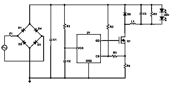
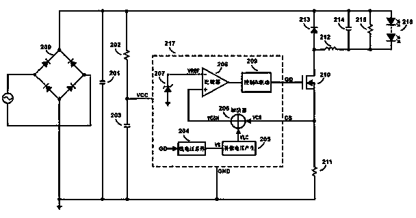
[0027] In order to solve the problems of low efficiency, high cost, large volume, and poor anti-interference ability of the traditional line voltage compensation technology, the present invention provides an integrated line voltage compensation circuit. The compensation circuit detects the conduction time of the power switch tube. The voltage on the bus is indirectly sampled, which saves the line voltage compensation resistor in the traditional technology, simplifies the system design of the external circuit, improves the system efficiency and reduces the system cost, and greatly improves the system's anti-interference ability and reliability.

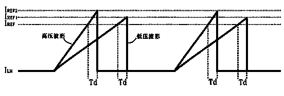
[0028] Due to the logic delay inside the control chip and the turn-off delay of the power switch tube, for the same LED constan...


PUM


Abstract

The invention discloses a line voltage compensation circuit used for LED drive. The circuit comprises a line voltage sampling unit, a compensation voltage generation unit, an inductance peak current sampling resistor, an adder unit, a comparator unit and a control and drive unit, wherein the line voltage sampling unit is used for sampling bus voltage of an LED constant current drive circuit, the compensation voltage generation unit is used for generating a compensation voltage value needed by the LED constant current drive circuit under the corresponding bus voltage, the inductance peak current sampling resistor is used for sampling peak currents of an inductor, the adder unit is used for adding the voltage value of peak current sampling resistance of the LED constant current drive circuit and the compensation voltage value generated by the compensation voltage generation unit, the comparator unit is used for generating an outage signal enabling a power switch tube to be shut down, and the control and drive unit is used for driving the power switch tube and carrying out constant current control on the whole LED constant current drive circuit. The line voltage compensation circuit omits line voltage compensation resistance in the traditional technology, and improves anti-interference performance and reliability of a system.

Description

[0001] technical field [0002] The invention relates to a line voltage compensation circuit, in particular to a line voltage compensation circuit for LED driving. [0003] Background technique [0004] The peak current control method is widely used in LED drive circuits to achieve constant current output, but due to the logic delay of the control chip and the turn-off delay of the power switch tube, these delays will cause inconsistent peak current under different bus voltages. Phenomenon, resulting in poor output constant current effect. [0005] The traditional solution is to add a line voltage compensation circuit outside the control chip, and realize output current compensation by directly detecting the voltage on the bus. The specific implementation method is to connect a resistor between the bus bar and the peak current sampling pin, and connect a resistor between the peak current sampling pin and the sampling resistor. According to different bus voltages, change t...

Claims


Application Information

Patent Timeline
IPC IPC(8): H05B37/02H02M3/156
Inventor 张明明黄彬阳
Owner 深圳市梓晶微科技有限公司
Why Eureka
Try Eureka