Sleeve for biological sample in-vitro purification treatment

A technology of biological samples and sleeves, applied in the field of biomedicine, can solve problems such as time-consuming and labor-intensive, unsolvable by centrifuge tubes, and difficult repeatability

Active Publication Date: 2014-06-11
BEIJING DONGFANG HUAHUI BIOMEDICAL TECH
View PDF6 Cites 4 Cited by
  • Summary
  • Abstract
  • Description
  • Claims
  • Application Information

AI Technical Summary

Problems solved by technology

The solution of pre-installed density media is indeed a good solution to the problem described in the above defect (a), but it also brings the following defects: (d) the storage method of this type of product must be designed separately for the density media Certainly
In summary, centrifuge tubes with a porous filter barrier structure pre-loaded with an appropriate density medium not only cannot solve the problems described in (b) and (c) in the above defects, but also introduce additional defects in (d) and (e) Issues of preservation, product safety and efficacy as described
[0009] Chinese patent 200610063125.4 provides a lymphocyte separation tube with a loose porous material at the bottom of the tube. The loose porous material can absorb the density medium into a semi-solid state. When the blood sample is purified, the blood sample can be directly poured into the tube. One kind of separation tube, without worrying about mixing the interface between the blood and the separation fluid, which solves the time-consuming and laborious problem of "spreading blood" operation
However, this

Method used


Image

  • Sleeve for biological sample in-vitro purification treatment
  • Sleeve for biological sample in-vitro purification treatment
  • Sleeve for biological sample in-vitro purification treatment

Examples


Embodiment 1

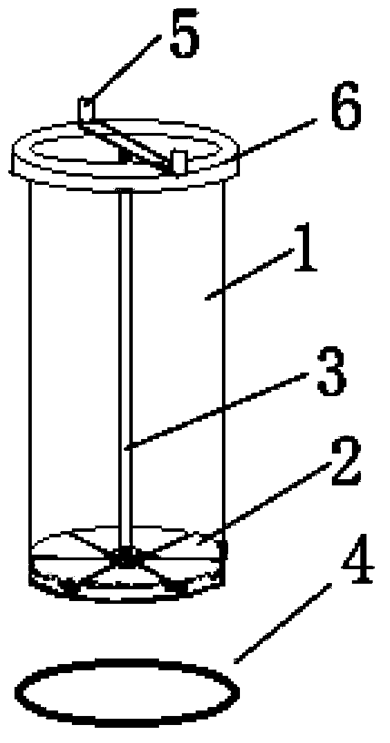
[0057] This embodiment provides a sleeve for in vitro purification of biological samples, which includes a tube body 1, six movable baffles 2, a connecting shaft 3, a sealing ring 4, and a coaxial locking switch 5, such as figure 1 shown, where:

[0058] The upper end of the pipe body 1 has an outward flange 6, and the bottom end face of the pipe body 1 is provided with several first openings 7 (such as Figure 5 As shown), the bottom end of its side wall is provided with several second openings 9 and several outward projections 8, wherein the projections 8 are located above the connecting parts 12 of two adjacent second openings 9 (such as Figure 6 shown);

[0059] The sealing ring 4 is a rubber ring, which is set on the outside of the second opening 9;

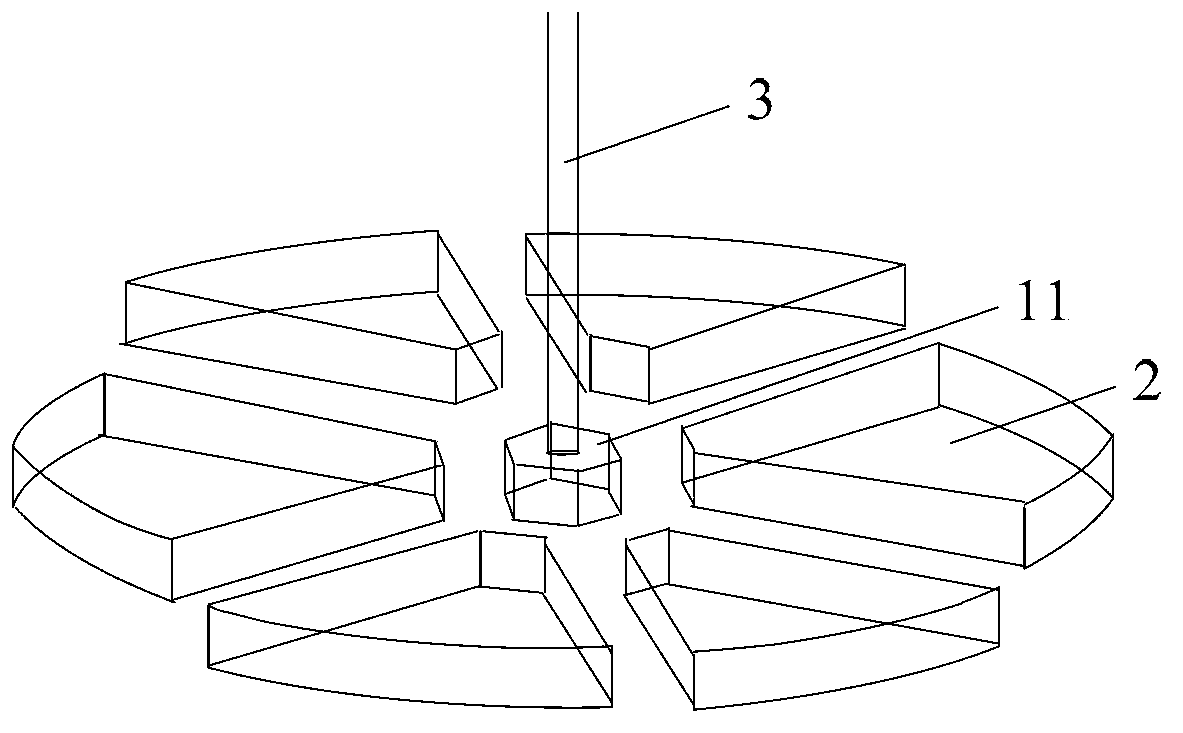
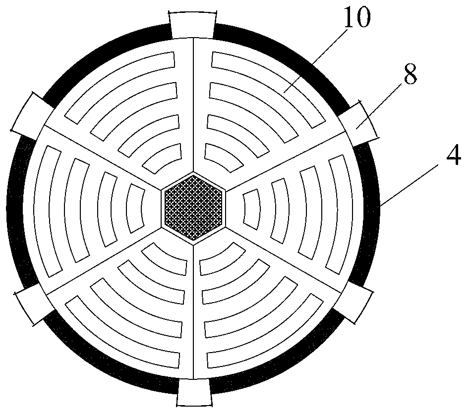
[0060] The movable baffle 2 is arranged at the bottom of the pipe body 1, which is in the shape of a ring fan, and a plurality of third openings 10 are arranged on it, and the outer edge of the movable baffle 2 correspond...

Embodiment 2

[0065] This embodiment provides a sleeve for in vitro purification of biological samples, wherein the structure of the movable baffle 2 and the polygonal part 11 is as follows: Figure 7 As shown, the movable baffle 2 includes a central part and an outer part, and the thickness of the central part is lower than that of the outer part. When the movable baffle 2 is combined together, a disc with a groove in the middle will be formed; the movable baffle 2 There is a groove on the outer end surface of the outer edge, which matches the size of the sealing ring 4, so that the sealing ring 4 can be placed on it to prevent slipping and displacement;

[0066] The polygonal part 11 is also thinner than the polygonal part 11 in Embodiment 1, and its size just matches the groove in the middle of the disc formed by the combination of the movable baffle 2. Other structures of the sleeve are the same as those in the embodiment. 1 is the same.

Embodiment 3

[0068] This embodiment provides a centrifuge tube for in vitro purification of biological samples, which includes a common centrifuge tube body and the sleeve provided in Embodiment 1 or 2, the sleeve is located in the centrifuge tube body and is movably matched with it .

[0069] Movable baffle 2 has two states of closing and opening, respectively as image 3 and Figure 4 As shown, wherein: when in the closed state, the six movable baffles 2 are combined with each other to form a circle with the polygonal part 11, and the sealing ring 4 is also in the contracted state at this time, and is sleeved on the second opening 9 of the pipe body 1. The outer side is in contact with the outer edge of the movable baffle 2, the first opening 7 at the bottom of the pipe body 1 and the third opening 10 on the movable baffle 2 do not have an overlapping area, and the pipe body 1 is in a relatively closed state; The shaft lock switch 5 can drive the connecting shaft 3 and the polygonal pa...


PUM


Abstract

The invention relates to a sleeve for biological sample in-vitro purification treatment. The sleeve comprises a pipe body, multiple movable baffles, a connecting shaft, a sealing ring and a coaxial locking switch, wherein the pipe body is cylindrical, a flange is arranged at the upper end of the pipe body, multiple first openings are formed in the end face of the bottom of the pipe body, and multiple second openings and convex blocks are arranged at the bottom end of the side wall of the pipe body; the sealing ring is sleeved on the outer side of the second openings; the movable baffles are arranged at the bottom of the pipe body, are of an annular fan shape and are provided with multiple third openings, and the outer edges of the third openings are in one-to-one correspondence with the second openings and are contacted with the sealing ring; the connecting shaft is positioned at a central position of the pipe body, the top end of the connecting shaft is connected with the coaxial locking switch, a polygonal part is arranged at the bottom end of the connecting shaft, and the edges of the polygonal part are in one-to-one correspondence with the inner edges of the movable baffles; the coaxial locking switch is positioned on the upper surface of the flange of the pipe body and can rotate. The sleeve provided in the invention is a device which is convenient, practical, low in production cost, simple in production process, safe and non-toxic and is used for biological sample in-vitro treatment.

Description

technical field [0001] The invention relates to a sleeve used for in vitro purification treatment of biological samples, which belongs to the technical field of biomedicine. Background technique [0002] The in vitro enrichment of biological particles in biological samples by centrifugation is one of the most widely used techniques in biological research. Many biological particles can be enriched by centrifugation, such as animal or plant cells, subcellular structures, bacteria, viruses or biomacromolecules. The behavior of these biological particles in suspension under centrifugation mainly depends on the size and density of the biological particles, which can be explained by the Stokes equation. The Stokes equation (see the following formula) describes the changing law of the motion velocity of spherical particles when they are subjected to centrifugal action in a liquid medium: [0003] v = d 2 ...

Claims


Application Information

Patent Timeline
IPC IPC(8): C12M1/24C12N5/078C12N5/0786C12N5/0789C12N5/0775
CPCC12M23/08C12M45/05
Inventor 赵侃王春有王冬明刘湘连甘朝
Owner BEIJING DONGFANG HUAHUI BIOMEDICAL TECH
Why Eureka
Try Eureka