Weaving machine transmission and weaving machine position automatic calibration system driven by switch reluctance motor

A technology of switched reluctance motor and automatic calibration system, used in looms, textiles, textiles and papermaking, etc., can solve the problems of frequent failures of main clutch and main brake, transmission belt breakage, and frequent failure of weft-seeking clutches.

Active Publication Date: 2014-06-11
浙江万利纺织机械有限公司 +1
View PDF9 Cites 5 Cited by
  • Summary
  • Abstract
  • Description
  • Claims
  • Application Information

AI Technical Summary

Problems solved by technology

[0012] But the above-mentioned existing transmission system has the following defects: when the loom speed reaches or exceeds about 450-500 rpm and the loom starts to brake, the main clutch and main brake fail frequently, or when the load of the open transmission system is very large , slow train, frequent failures of the weft-seeking clutch, broken transmission belt, etc., which limit the maximum speed of the loom; if the speed of the loom is changed, the pulley needs to be replaced or the frequency conversion motor is used, and variable-speed weaving cannot be realized. Normal weaving and weft-seeking movement , Slow motion adopts different transmission routes, and the mechanical structure is complex; the zero position of the spindle encoder representing the position of the loom needs to be manually calibrated

Method used


Image

  • Weaving machine transmission and weaving machine position automatic calibration system driven by switch reluctance motor
  • Weaving machine transmission and weaving machine position automatic calibration system driven by switch reluctance motor
  • Weaving machine transmission and weaving machine position automatic calibration system driven by switch reluctance motor

Examples


Embodiment Construction

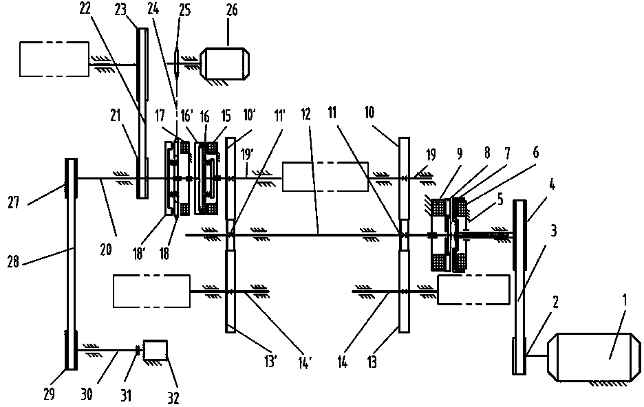
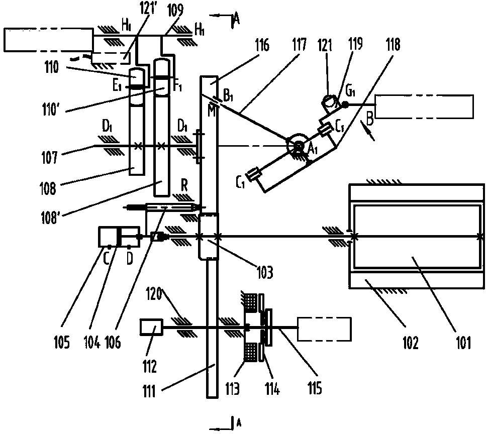
[0029] The present invention will be described in detail below in conjunction with the accompanying drawings: the present invention is mainly to overcome the deficiencies of the prior art. On the basis of the prior art—the rapier loom drive system driven by the switched reluctance motor, the main clutch, the main Brakes, weft-seeking clutches, idle clutches, etc., cancel the belt drive; see the specific drive system figure 2 -6 shown.

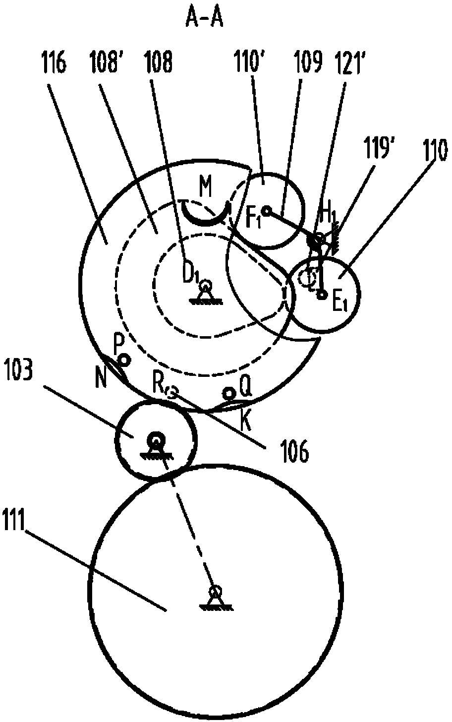
[0030] The loom transmission and loom position automatic calibration system driven by the switched reluctance motor, the motor stator 102 of the switched reluctance motor is fixed on the frame 120, the motor rotor 101 and a main motor supported on the frame 120 through bearings The gear shaft 103 is fixedly connected, and it is characterized in that: one end of the gear shaft 103 of the main motor is connected with a piston 104 through a bearing, and the piston 104 is fixedly connected with a movable pin 106 placed in the guide hole R on the f...


PUM


Abstract

The invention provides a weaving machine transmission and weaving machine position automatic calibration system driven by a switch reluctance motor. A motor stator of the switch reluctance motor is fixedly arranged on a machine frame, the motor rotor is fixedly connected with a main motor gear shaft supported on the machine frame through a bearing, one end of the main motor gear shaft is connected with a piston through a bearing, and the piston is fixedly connected with a movable insertion pin arranged in a guide hole formed in the machine frame, so the insertion pin forms cylinder pair connection with the machine frame, the piston is arranged in a piston cylinder fixedly arranged on the machine frame, in addition, the cylinder pair connection is formed, the piston is matched with the insertion pin, and can transversely move but cannot rotate; the main motor gear shaft is engaged with an opening transmission gear fixedly connected onto an opening transmission shaft through a shaft gear, the opening transmission shaft is fixedly connected with an armature of an opening brake through a spring, the two ends of the opening transmission shaft are respectively connected with an encoder and an opening mechanism, and a coil of the opening brake is fixedly connected with the machine frame. The weaving machine transmission and weaving machine position automatic calibration system has the characteristics that the mechanism is reasonable, the use is convenient and reliable, the speed of a weaving machine can be accelerated, the speed change and position calibration automation degree of the weaving machine can be improved, and the like.

Description

technical field [0001] The invention relates to a loom transmission and loom position automatic calibration system driven by a switched reluctance motor, and a transmission and control technology in the field of textile machinery. Background technique [0002] Conventional rapier looms use a three-phase asynchronous AC motor to drive the main shaft of the loom, and a clutch brake is used to realize the starting and braking function of the loom. The speed of the loom is changed by changing the speed ratio or changing the driving frequency of the motor. [0003] figure 1 Shown is a transmission system in the prior art, wherein, the output shaft of the three-phase asynchronous AC main motor 1 is fixedly connected with the main drive pulley 2; the main clutch rotor 7 is fixedly connected with the main drive pulley 4, and is connected with the The high-speed gear shaft 11 is connected; the clutch brake armature 8 is fixedly connected to the high-speed gear shaft 11 through a spr...

Claims


Application Information

Patent Timeline
Patent Type & Authority Applications(China)
IPC IPC(8): D03D51/00
Inventor 周香琴王琴龙万祖干
Owner 浙江万利纺织机械有限公司
Why Eureka
Try Eureka