Damping devices for gas turbine combustors

A damping device and gas turbine technology, applied in gas turbine devices, jet propulsion devices, combustion chambers, etc., can solve the problem of high manufacturing costs, reduce manufacturing risks, optimize cooling and service life performance, and achieve effective damping effects

Active Publication Date: 2016-01-20
ANSALDO ENERGIA SWITZERLAND AG
View PDF8 Cites 1 Cited by
  • Summary
  • Abstract
  • Description
  • Claims
  • Application Information

AI Technical Summary

Problems solved by technology

The disadvantage of this solution is that, due to the shape of the near-wall cooling channels, the part will be made of several layers which eventually have to be brazed together
Manufacturing costs are several times higher compared to casting processes where the use of ceramic cores can be avoided

Method used


Image

  • Damping devices for gas turbine combustors
  • Damping devices for gas turbine combustors
  • Damping devices for gas turbine combustors

Examples


Embodiment Construction

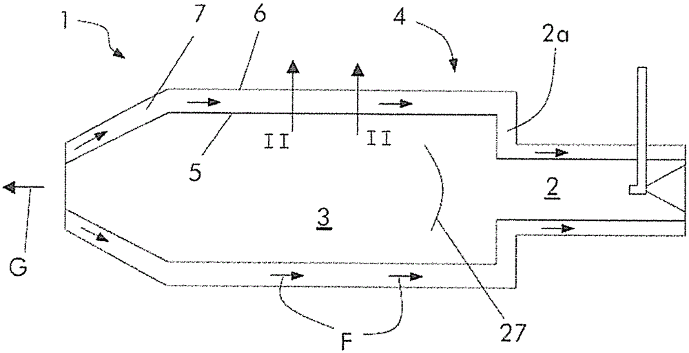
[0042] figure 1 A reheat combustor 1 of a gas turbine with sequential combustion according to the prior art is shown. The burner 1 comprises a burner section 2 axially connected to a combustion chamber 3 . The hot gas flow entering the burner section 2 is fueled by means of fuel supply injectors (eg fuel lances) extending into the hot gas flow and then flows along the mixing zone. The mixture formed in the mixing zone leaves the burner section 2 at its outlet to expand into the combustion chamber 3 . In the combustor 3 the mixture is combusted in a flame 27 generating hot gases G which are expanded in a turbine (not shown).

[0043] The interface between the burner section 2 and the combustion chamber 3 is characterized by a regularly abrupt change in cross-sectional area comprising a vertical front plate extending from the outlet of the burner section 2 to the peripheral wall of the combustion chamber 3 2a. At least a part 4 of the burner wall comprising the burner sectio...


PUM


Abstract

The present invention relates to damping arrangements for gas turbine combustors. It comprises: a wall having a first inner wall and a second outer wall arranged at a distance from each other; a plurality of cooling channels extending substantially parallel between the first inner wall and the second outer wall; and at least one damping space composed of The cooling channel delimits, further comprising a first passage for supplying cooling medium from the cooling channel into the damping space and a second passage for connecting the damping space to the combustion chamber, characterized in that the end plate fixed to the inner wall will The damping space is separated from the combustion chamber, said end plate is provided with a neck passage and additionally at least one supply plenum for a cooling medium, at least one outlet plenum for a cooling medium and at least one cooling passage, said At least one cooling passage enables a cooling medium to flow from at least one supply plenum to another supply plenum or to at least one outlet plenum.

Description

technical field [0001] The present invention relates to the field of gas turbines, and in particular to lean premixed, low emission combustion systems having one or more means for suppressing thermo-acoustically induced pressure oscillations in the high frequency range, which means must be suitably Cooling to ensure well-defined damping performance and sufficient service life. Background technique [0002] A disadvantage of lean premixed, low emission combustion systems in gas turbines is that they present an increased risk of generating thermoacoustically induced combustion oscillations. Such oscillations, which have been a well-known problem since the early days of gas turbine development, are due to strong coupling between fluctuations in heat release rate and pressure, and can cause mechanical and thermal damage and limit operating conditions. [0003] One possibility to suppress such oscillations consists in attaching damping means such as quarter wave tubes, Helmholtz...

Claims


Application Information

Patent Timeline
Patent Type & Authority Patents(China)
IPC IPC(8): F23R3/00
CPCF23R3/002F23R2900/00014F23M20/005F01D25/00F02C7/24F23R3/26F05D2260/963F23R3/00F23R3/42
Inventor M.T.莫勒U.本兹M.R.博希恩
Owner ANSALDO ENERGIA SWITZERLAND AG
Why Eureka
Try Eureka