Method for increasing target detection probability of radar signal

A radar signal and target detection technology, which is applied in the direction of measuring devices, radio wave measurement systems, radio wave reflection/reradiation, etc., to reduce the probability of false alarms, improve performance, and reduce the probability of false detection

Inactive Publication Date: 2016-05-25
HYUNDAI MOBIS CO LTD
View PDF5 Cites 0 Cited by
  • Summary
  • Abstract
  • Description
  • Claims
  • Application Information

AI Technical Summary

Problems solved by technology

[0005] As a method for CFAR detection, there are various CFARs such as CA-CFAR and OS-CFAR, but conventionally, only one sample (TestCell) used in CFAR detection is commonly used

Method used


Image

  • Method for increasing target detection probability of radar signal
  • Method for increasing target detection probability of radar signal
  • Method for increasing target detection probability of radar signal

Examples


Embodiment Construction

[0035] Hereinafter, the present invention constituted as above will be described in detail with reference to the accompanying drawings.

[0036] In this process, for the sake of clarity and convenience of description, the thickness of lines shown in the drawings, the size of components, and the like may be shown exaggeratedly. In addition, the terms described later are terms defined in consideration of functions in the present invention, and may vary depending on the user's or operator's intention or practice. Therefore, these terms should be defined on the basis of the entire content of this specification.

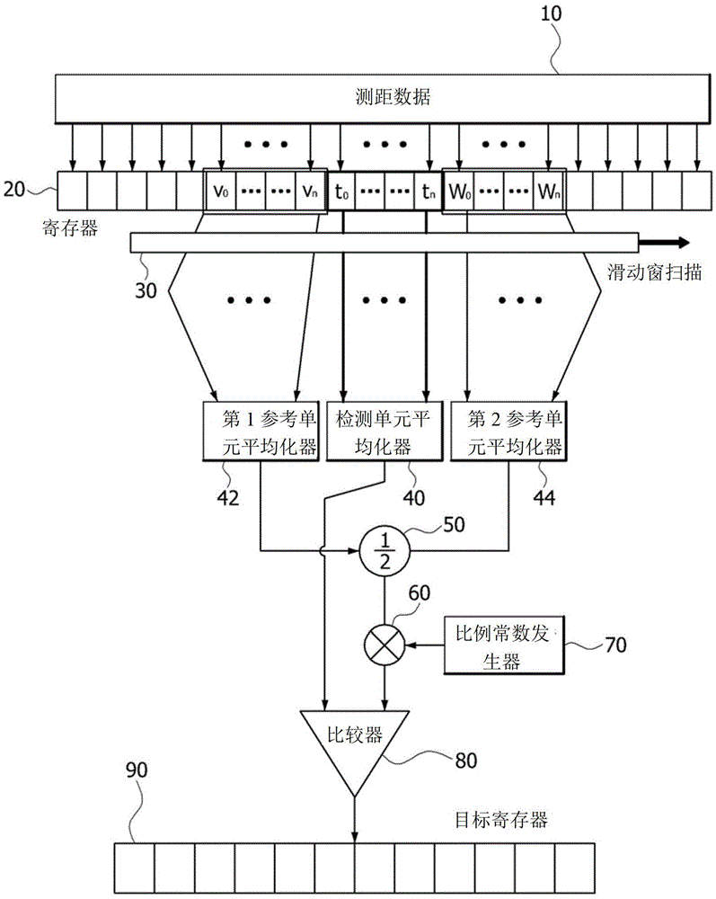
[0037] image 3 It is a diagram showing the configuration of a radar signal target detection device to which a method for increasing the target detection probability of a radar signal according to an embodiment of the present invention is applied.

[0038] Such as image 3 As shown, the radar signal target detection device of the method for increasing the target detect...


PUM


Abstract

The present invention is characterized in a method comprises a first step of arranging data positions as cell data forms by using distances as indexes by a register after inputting Range Data of a radar signal; a second step of scanning the register by a Sliding Window, assigning at least more than one Test Cell, and assigning at least more than one Reference Cell; a third step of respectively comparing data values of the Test Cells and data values of the Reference Cells by a comparator; and a fourth step of processing the Test Cells having the data values smaller than that of the Reference Cells as noises, according comparative results of the comparator, by determining the Test Cells having the data values larger than that of the Reference Cells as target data.

Description

technical field [0001] The present invention relates to a method for increasing the target detection probability of radar signals, and more specifically, relates to a method that can minimize the target misdetection of short-distance targets in the CFAR (Constant FalseAlamRate, Constant False Alarm Rate) of radar devices. , a method of increasing the probability of target detection of a radar signal by increasing the probability of detection. Background technique [0002] Generally speaking, CFAR (ConstantFalseAlamRate) applied to radar is used as a method to determine the threshold (Threshold) of the received signal, comparing the surrounding distance (ReferenceCell, reference unit) and the signal used to judge whether there is a target (TestCell, detection unit) According to the comparison result, it is distinguished whether the received signal is noise or target signal. [0003] On the other hand, the radar sends radio waves, and the received signal includes not only the...

Claims


Application Information

Patent Timeline
Patent Type & Authority Patents(China)
IPC IPC(8): G01S7/02G01S13/06
CPCG01S7/2927G01S13/931B60W2420/52
Inventor 金世允
Owner HYUNDAI MOBIS CO LTD
Why Eureka
Try Eureka