
Finfet and its manufacturing method

A finfet and semiconductor technology, applied in semiconductor/solid-state device manufacturing, semiconductor devices, electrical components, etc.

Active Publication Date: 2016-12-21
INST OF MICROELECTRONICS CHINESE ACAD OF SCI
View PDF5 Cites 0 Cited by
  • Summary
  • Abstract
  • Description
  • Claims
  • Application Information

AI Technical Summary

Problems solved by technology

However, ion implantation performed to form the punch-through preventing layer may introduce undesired dopants in the channel region of the semiconductor fin
This additional doping results in random dopant concentration fluctuations in the channel region of the FinFET

Method used


Image

  • Finfet and its manufacturing method
  • Finfet and its manufacturing method
  • Finfet and its manufacturing method

Examples


Embodiment Construction

[0016] Hereinafter, the present invention will be described in more detail with reference to the accompanying drawings. In the various figures, identical elements are indicated with similar reference numerals. For the sake of clarity, various parts in the drawings have not been drawn to scale.

[0017] For the sake of simplicity, the semiconductor structure obtained after several steps can be described in one figure.

[0018] It should be understood that when describing the structure of a device, when a layer or a region is referred to as being "on" or "over" another layer or another region, it may mean being directly on another layer or another region, or Other layers or regions are also included between it and another layer or another region. And, if the device is turned over, the layer, one region, will be "below" or "beneath" the other layer, another region.

[0019] If it is to describe the situation of being directly on another layer or another area, the expression "d...


PUM


Abstract

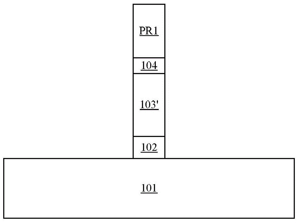
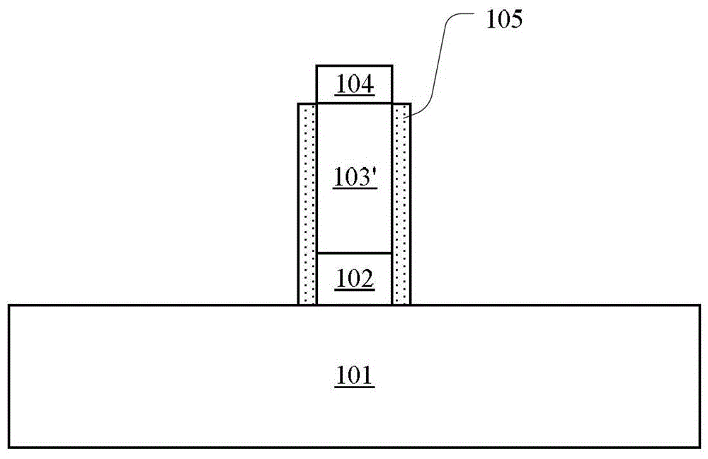
The invention discloses a fin field effect transistor (FinFET) and a manufacturing method thereof. The manufacturing method of the FinFET includes the following steps that: a first semiconductor layer is formed on a semiconductor substrate; a second semiconductor layer is formed on the first semiconductor layer; a top protection layer is formed on the second semiconductor layer; the second semiconductor layer is patterned, such that a semiconductor fin can be formed; a sidewall protection layer is formed on a side surface of the semiconductor fin; the first semiconductor layer is doped, such that a doped punch-through-stopper layer can be formed; the top protection layer and the sidewall protection layer are removed; a gate stack that spans the semiconductor fin is formed, and the gate stack includes a gate dielectric and a gate conductor, and the gate conductor and the semiconductor fin are separated from each other by the gate dielectric; a gate sidewall surrounding the gate conductor is formed; and a source region and a drain region are formed in portions of the semiconductor fin which are located at two sides of the gate stack. The semiconductor fin is separated from the semiconductor substrate through the doped punch-through-stopper layer, and therefore, the height of the semiconductor fin can be controlled with easiness, and a leakage current path which is located between the source region and the drain region and passes through the semiconductor substrate can be disconnected.

Description

technical field [0001] The present invention relates to semiconductor technology, and more particularly, to FinFETs and methods of making the same. Background technique [0002] As the size of semiconductor devices becomes smaller and smaller, the short channel effect becomes more and more obvious. To suppress short-channel effects, FinFETs formed on SOI wafers or bulk semiconductor substrates have been proposed. A FinFET includes a channel region formed in the middle of a fin (fin) of semiconductor material, and source / drain regions formed at both ends of the fin. The gate electrode surrounds the channel region on both sides of the channel region (ie a double gate structure), thereby forming an inversion layer on each side of the channel. Since the entire channel region can be controlled by the gate, it can play a role in suppressing the short channel effect. [0003] In mass production, FinFETs fabricated using semiconductor substrates are more cost-effective than using...

Claims


Application Information

Patent Timeline
Patent Type & Authority Patents(China)
IPC IPC(8): H01L21/336H01L29/78H01L29/06
Inventor 朱慧珑许淼梁擎擎尹海洲
Owner INST OF MICROELECTRONICS CHINESE ACAD OF SCI
Learn More