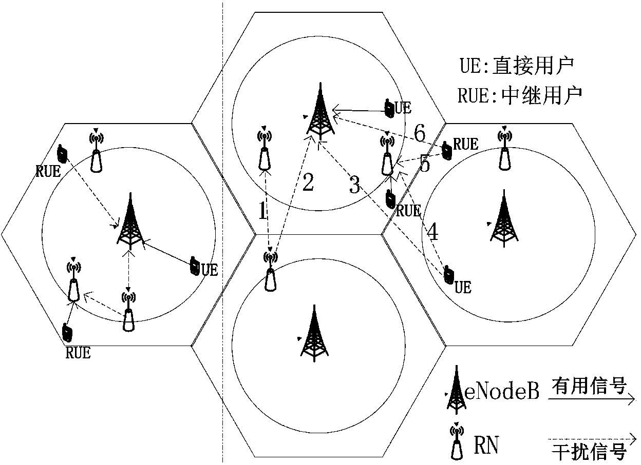
Uplink interference coordination method of LET-Advanced relay system
A technology for interference coordination and relay systems, applied in power management, electrical components, wireless communications, etc., can solve problems such as poor user satisfaction, low spectrum utilization, and low network throughput, so as to improve system throughput and improve Spectrum utilization and the effect of reducing uplink interference
- Summary
- Abstract
- Description
- Claims
- Application Information
AI Technical Summary
Problems solved by technology
Method used
Image
Examples
Embodiment 1
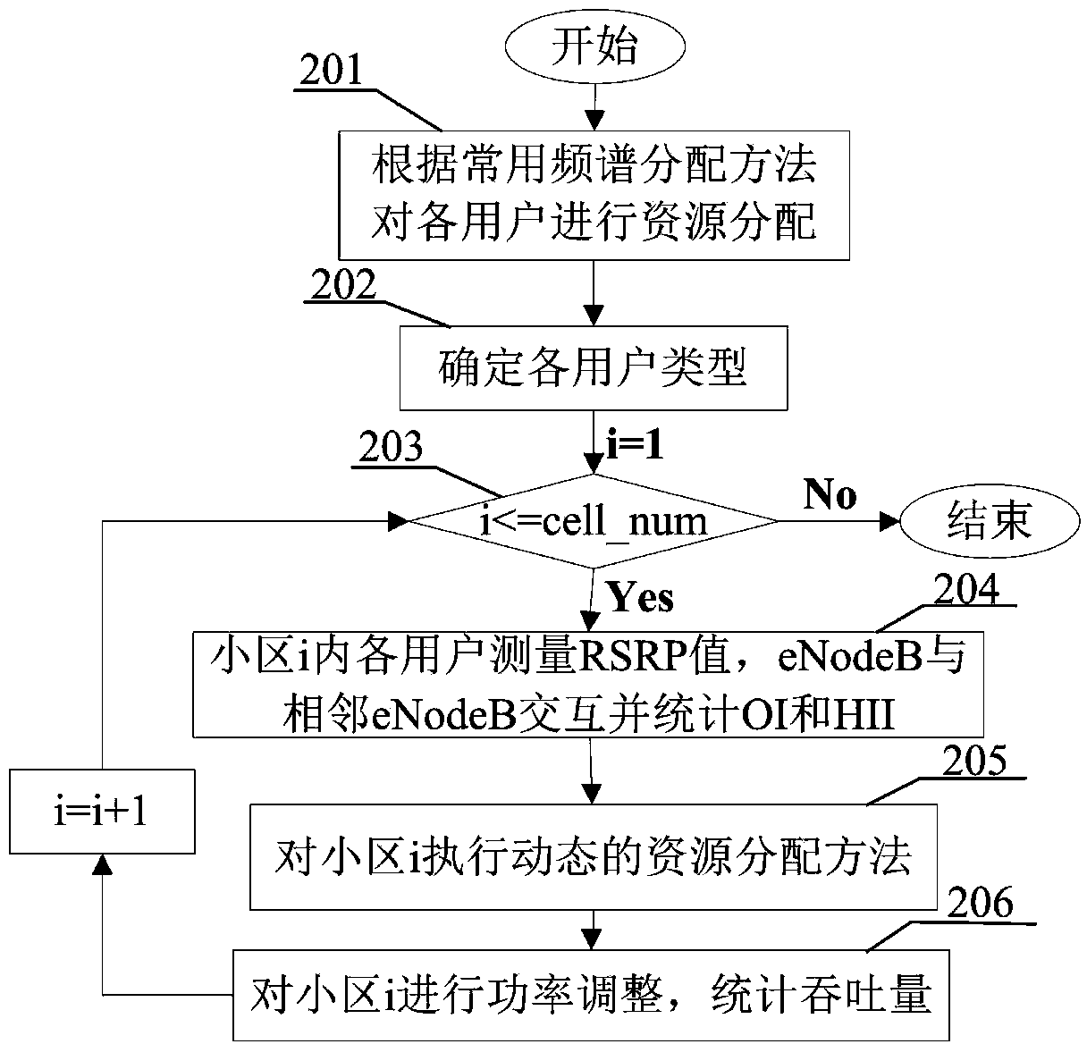
[0020] figure 2 It is a flow chart of the uplink interference coordination method applicable to the LTE-Advanced relay system of the present invention, comprising the following steps:
[0021] Step 201: Initially allocate spectrum resources to each user in each cell in the LTE-Advanced relay system;
[0022] Step 202: Combining the OI information and the RSRP value to determine the type of each user UE in the cell, whether it is a direct UE or a relay UE;
[0023] Step 203: judging whether operations such as dynamic spectrum allocation and power adjustment have been performed successively on each cell in the LTE-Advanced relay system, if yes, the operation ends, if otherwise, perform step 204;
[0024] Step 204: According to the result of step 201 and the user type determined in step 202, HII information is counted;
[0025] Step 205: The cell eNodeB executes a dynamic spectrum allocation strategy in combination with step 204;
[0026] Step 206: Perform open-loop power adj...
Embodiment 2
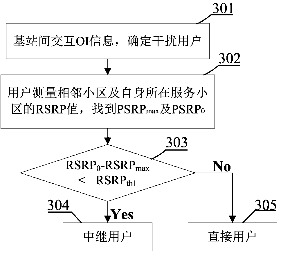
[0028] image 3 It is a flowchart of user type determination involved in the present invention, and the method includes the following steps:
[0029] Step 301: The eNodeB detects PRBs in the cell that are subject to uplink interference, and passes X 2 The interface (that is, the interface between the base station and the base station) sends OI information (Overload Indicator, OI for short) to the adjacent cell. The OI information indicates the PRB that is highly interfered by the adjacent cell, thereby determining the interfering user;
[0030] Step 302: According to the result obtained in step 301, measure the RSRP values of all neighboring cells and the cell where the user is located for each of the users who are determined to cause interference; find out the maximum value of the RSRP values of the neighboring cells, and record it as RSRP max ; Denote the RSRP of the serving cell as RSRP 0 ;
[0031] Step 303: RSRP max with RSRP 0 Compare to determine the main inter...
Embodiment 3
[0038] Figure 5 It is a flowchart of dynamic spectrum allocation involved in the present invention, and the process includes the following steps:
[0039] Step 501: Count the HII information shared between cells, and obtain the list of PRBs vulnerable to interference of relay UEs in neighboring cells;
[0040] Step 502: Combine the bandwidth allocation of the relay UE in the current cell with the execution result of step 501, find out the PRB that is free and will not interfere with the relay UE in the neighboring cell, and record it as the free resource block set FPRB s ;
[0041] Step 503: From FPRB s Select the PRB to reassign to the interfering relay user; (
[0042] Step 504: judging whether there are remaining free resource blocks, if yes, execute step 505, if otherwise, execute step 506;
[0043] Step 505: set the FPRB s The remaining PRBs in are allocated to direct users;
[0044] Step 506: The dynamic resource allocation ends.
PUM
 Abstract
Description
Claims
Application Information
 - R&D
- Intellectual Property
- Life Sciences
- Materials
- Tech Scout
- Unparalleled Data Quality
- Higher Quality Content
- 60% Fewer Hallucinations
Browse by: Latest US Patents, China's latest patents, Technical Efficacy Thesaurus, Application Domain, Technology Topic, Popular Technical Reports.
© 2025 PatSnap. All rights reserved.Legal|Privacy policy|Modern Slavery Act Transparency Statement|Sitemap|About US| Contact US: help@patsnap.com


