System for operating an electric tractive unit

A technology for operating systems and electric locomotives, which is applied in the field of systems for operating electric locomotives and vehicles to achieve the effect of small structure size and reliable transmission

Inactive Publication Date: 2014-06-11
SIEMENS MOBILITY GMBH
View PDF7 Cites 4 Cited by
  • Summary
  • Abstract
  • Description
  • Claims
  • Application Information

AI Technical Summary

Problems solved by technology

Furthermore, when the section switch is arranged in the acceleration area of ​​the traveling line, for example in the vicinity of a station location, th

Method used


Image

  • System for operating an electric tractive unit
  • System for operating an electric tractive unit
  • System for operating an electric tractive unit

Examples


Embodiment Construction

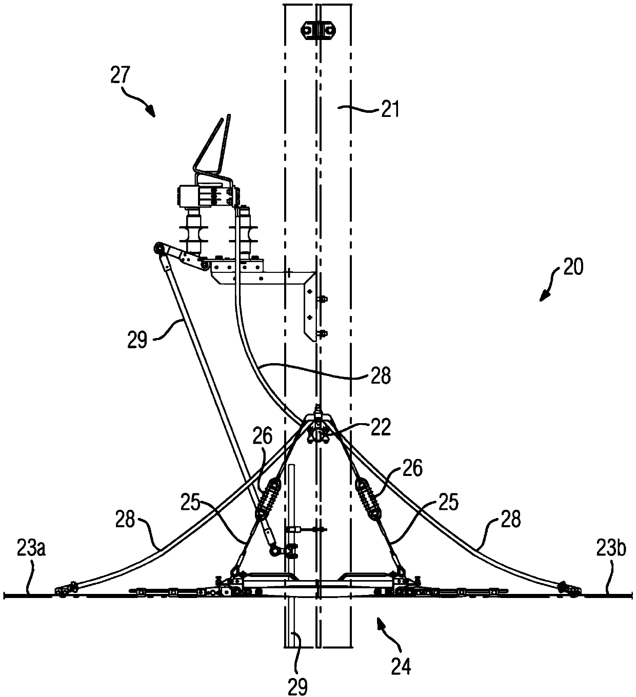
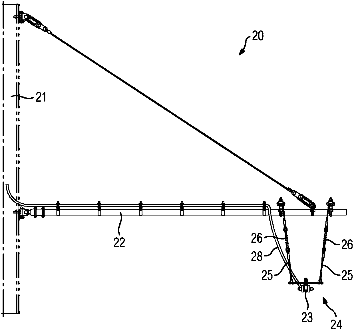
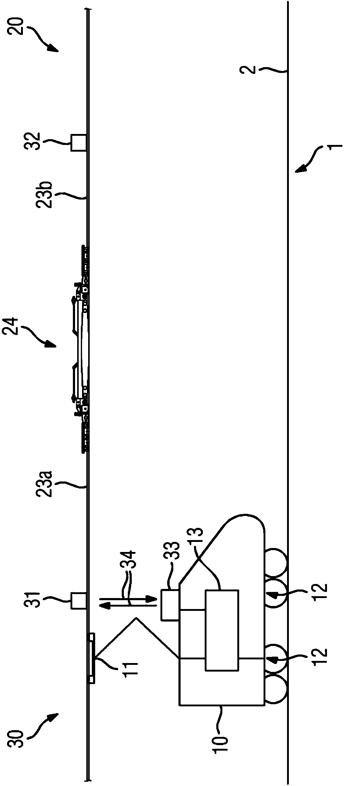
[0031] according to image 3 The electric rolling stock 10, such as short-distance traffic rail electric rolling stock, is passed according to figure 1 and figure 2 The contact wire device 20 is supplied with electrical energy. The contact line system 20 is designed as an overhead line system with a contact line 23 carried by a catenary system. For this purpose, a line pylon 21 is erected along the track 2 of the electric rolling stock 10 , on which a cantilever frame 22 protruding laterally from the track 2 is rotatably supported. In the region of the illustrated wire tower 21, the contact wire arrangement 20 has a separation point in which the contact wire 23 formed as an antenna wire is divided into two contact wire parts 23a and 23b which are electrically isolated from each other . The contact conductor arrangement 20 has a section switch 24 in a separating position, via which the contact conductor parts 23a and 23b are connected to each other in an insulated manner. ...


PUM


Abstract

System for operating an electric tractive unit. The invention relates to a system (1) for operating an electric tractive unit (10), having a contact line system (20) which is arranged along a route (2) of the tractive unit (10). In this context, a current collector (11) of the tractive unit (10) for transmitting energy can be placed in sliding contact with a contact line (23) of the contact line system (20). In addition, the contact line (23) is divided by a section insulator (24), along which the current collector (11) can travel with sliding contact, into contact line sections (23a, 23b) which are supplied with electricity separately from one another. According to the invention, a detection device (30) is designed to detect when travel over the section insulator (24) by tractive unit (10) is imminent. Said detection device (30) interacts with a drive controller (13) for an electric drive (12) of the tractive unit (10) in such a way that transmission of energy via the current collector (11) while the section insulator (24) is being travelled over is automatically reduced or switched off. As a result, the wear on section insulators (24) can be reduced.

Description

technical field [0001] The invention relates to a system for operating an electric rolling stock according to the preamble of claim 1 . Background technique [0002] The energy supply of electric rolling stock, in particular rail vehicles or light rail vehicles, takes place via contact conductor systems. In this case, the substation converts the supply voltage of the power supply network into a contact conductor voltage and feeds it into the contact conductors, for example into the conductor rails of an overhead line installation or into conductor rails arranged laterally on the track. For operational or technical reasons, the contact conductors are divided by the separation points into contact conductor parts which form supply parts which are supplied separately from one another. [0003] The disconnected position is achieved by means of a so-called section switch, which can be moved over by the pantograph of the electric rolling stock in sliding contact, and the longitudi...

Claims


Application Information

Patent Timeline
IPC IPC(8): B60M1/18B60L3/06B60L7/06B60L9/16
CPCB60M1/18B60L2240/12B60L9/16B60L7/06B60L2200/26
Inventor A.多灵
Owner SIEMENS MOBILITY GMBH
Why Eureka
Try Eureka