
Indirect thermal control device for high resolution optical remote sensor precision temperature control

An optical remote sensor and high-resolution technology, which is applied in the direction of control devices for the living conditions of aerospace vehicles, can solve the problems of high energy consumption and difficulty in meeting the demand for precise temperature control, and achieve the goal of reducing temperature fluctuations and improving temperature stability Effect

Active Publication Date: 2014-06-18
BEIJING RES INST OF SPATIAL MECHANICAL & ELECTRICAL TECH
View PDF4 Cites 17 Cited by
  • Summary
  • Abstract
  • Description
  • Claims
  • Application Information

AI Technical Summary

Problems solved by technology

In addition, for the main control temperature control loop directly loaded on the controlled object, it is limited by the temperature measurement response time and temperature measurement accuracy of the existing aerospace application temperature measurement equipment, and the temperature control accuracy of the temperature control equipment. The temperature control method can only control the temperature of the controlled object within the range of ±0.3°C to ±2°C
[0005] With the development of remote sensors towards large aperture, high energy consumption, high heat flux density, and high temperature control accuracy, high-resolution remote sensors have proposed temperature control accuracy requirements better than ±0.1°C for the main optical-mechanical structure. Traditional temperature control methods Difficult to meet the precise temperature control requirements

Method used


Image

  • Indirect thermal control device for high resolution optical remote sensor precision temperature control
  • Indirect thermal control device for high resolution optical remote sensor precision temperature control

Examples


Embodiment Construction

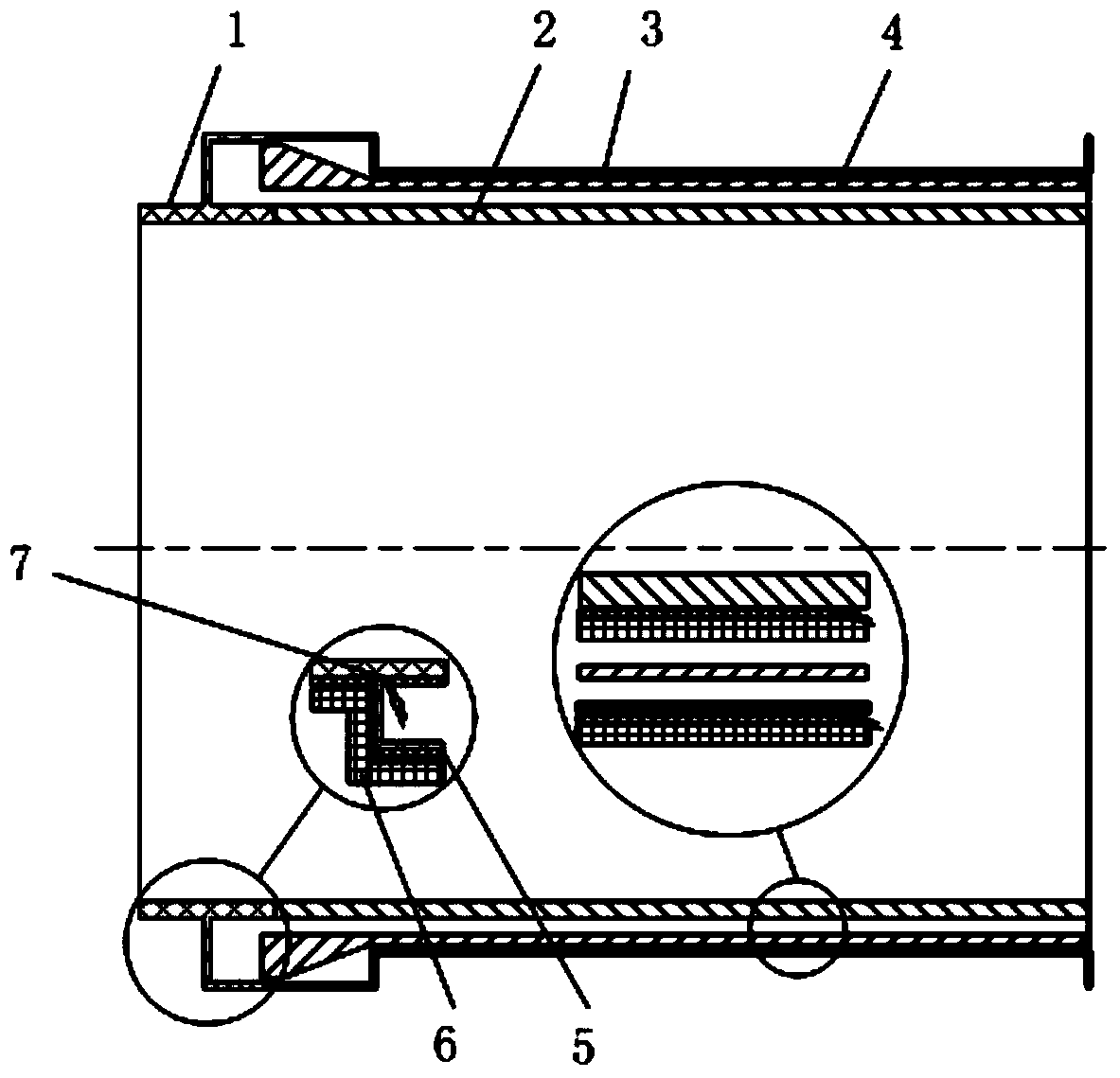
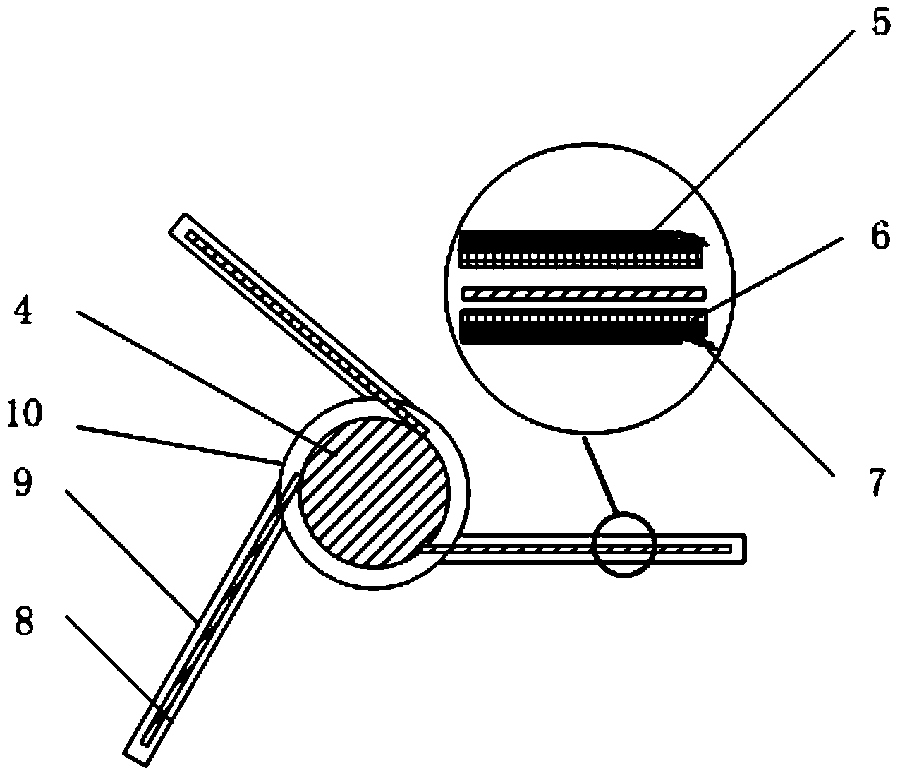
[0012] The present invention designs a thin-walled blackened heat shield structure around the controlled object requiring high temperature stability, and performs conventional heat insulation and temperature control circuit design on the heat shield structure, so that the temperature of the heat shield structure fluctuates within a certain threshold range. Through the radiation heat exchange between the heat shield structure and the controlled object, the temperature fluctuation of the controlled object can be effectively reduced, and the precision temperature control effect of the high-resolution optical remote sensor lens and the optical machine body can be improved, so that it can reach a temperature better than ±0.1°C temperature stability.

[0013] figure 1 Schematic diagram of the application of indirect thermal control to a commonly used lens barrel assembly in high-resolution optical remote sensors. It includes a heat shield structure, a controlled object 4, a thin fi...


PUM


Abstract

The invention discloses an indirect thermal control device for high resolution optical remote sensor precision temperature control. The indirect thermal control device comprises a thermal cover structure, a thin film electric heater, a temperature measuring element, a multi-layer thermal insulation assembly and a temperature control instrument circuit. The thermal cover structure is installed on the periphery of a controlled object in a thermal insulation mode, the thin film electric heater and the temperature measuring element are stuck on the thermal cover structure, the temperature reading number fed back by the temperature measuring element is read through a temperature control instrument, and active temperature control over the thermal cover structure is achieved through a control loop. The thermal cover structure is coated with the multi-layer thermal insulation assembly, and the influence of environmental temperature fluctuation on the temperature of the thermal cover structure is reduced. The temperature of the thermal cover structure is controlled to fluctuate within the temperature control threshold value range. By means of radiant heat exchange between the surface of the thermal cover structure and the controlled structure, temperature control over the controlled object is achieved. The indirect thermal control device for high resolution optical remote sensor precision temperature control controls the temperature of the controlled object through active temperature control over the thermal cover structure and radiant heat exchange between the thermal cover structure and the controlled object.

Description

technical field [0001] The invention belongs to the technical field of thermal control of aerospace optical remote sensors, and relates to an indirect thermal control device for precise temperature control of high-resolution optical remote sensors. Background technique [0002] my country's space optical remote sensing satellite images have been widely used in many fields and played an inestimable role. With the further deepening of the application, users have higher and higher requirements for image quality. In order to achieve higher image quality, high-resolution optical remote sensors need to meet higher geometric accuracy, so higher requirements are placed on the degree of precise temperature control of remote sensors. Not only are the requirements for the temperature level of the remote sensor more stringent, but also the temperature stability requirements for the remote sensor are greater. Therefore, it is required to precisely control the temperature of the key str...

Claims


Application Information

Patent Timeline
Patent Type & Authority Applications(China)
IPC IPC(8): B64G1/50
Inventor 宋欣阳高娟赵振明鲁盼李春林罗世魁曹东晶
Owner BEIJING RES INST OF SPATIAL MECHANICAL & ELECTRICAL TECH
Learn More