
Methods of soil dehydration, drying or solidification

A soil and drying technology, applied in the field of foundation reinforcement and soil dehydration, to achieve the effect of reducing yard, good drying effect, and shrinking garbage volume

Active Publication Date: 2015-10-14
YIXING LIANGXU WELDING CERAMIC PART
View PDF7 Cites 0 Cited by
  • Summary
  • Abstract
  • Description
  • Claims
  • Application Information

AI Technical Summary

Problems solved by technology

But its shortcomings are also obvious: the existing vacuum preloading adopts the upper row type for drainage. In the process of drainage, gravity and the resistance of filter cloth and drainage channels to water must be overcome, and the effect will be reduced after drying to a certain degree in the later stage. Tend to stop

Method used


Image

  • Methods of soil dehydration, drying or solidification
  • Methods of soil dehydration, drying or solidification
  • Methods of soil dehydration, drying or solidification

Examples


Embodiment 1

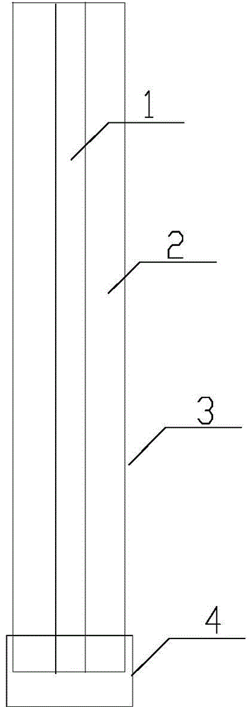
[0036] Such as figure 1 Shown: a vacuum panel, the main body of the vacuum panel is a skeleton 2; several drainage grooves 5 are provided on the skeleton 2, and a vacuum drainage channel 1 is also provided; the surface of the skeleton 2 is covered with a permeable water-permeable layer 3; the vacuum The end of the plate is provided with a joint 4, and there is a cavity inside the joint 4, and a closed structure is formed between the joint 4 and the end of the vacuum plate, and the end of all drainage grooves 5 on the skeleton 2 and the end of the vacuum drainage channel 1 and the cavity of the joint 4 Connected; the top of the vacuum drainage channel 1 is connected to the vacuum pipe network. The material of the frame 2 is plastic or steel pipe; the permeable material is geotextile.

[0037] Such as Figure 2-4 As shown, the cross section of the vacuum drainage channel 1 is rectangular, the number of the vacuum drainage channel 1 can be one or several, and the relative posit...

Embodiment 2

[0041] In this embodiment, the volume of the drying pool is 10m 3 , the specific steps are as follows:

[0042] (1) Pre-treatment: transport Taihu Lake silt to the drying tank for preliminary sedimentation, and lay woven cloth on the mud surface;

[0043] (2) the setting of vacuum board: insert several vacuum boards in the silt gained in step (1), and the vacuum drainage channel airtight in the vacuum board is connected with the vacuum pipe network;

[0044] (3) Vacuuming: lay geotextile protection vacuum pipe network on the silt that has laid vacuum board in step (2), and seal with sealing film;

[0045] (4) Vacuuming: Vacuumize the vacuum plate through the vacuuming pipe network until the water output is significantly less and the mud surface has no obvious drop and change; stop vacuuming;

[0046] (5) Post-processing: After the sealing film is uncovered, the top of the vacuum plate is connected to the atmosphere, and the suction treatment is continued to accelerate the fl...

Embodiment 3

[0051] In this embodiment, the volume of the drying tank is 100m 3 , the specific steps are the same as in Example 1.

[0052] The specific parameters are shown in Table 2.

[0053] Table 2

[0054] The initial mud content of silt


PUM


Abstract

The invention relates to a soil dehydration desiccation or solidification method, and belongs to the field of soil dehydration and foundation reinforcement. According to the method, a specially-designed vacuum plate is inserted in soil, then moisture in the soil is discharged through a vacuum preloading process, at last, a sealing film is removed, a vacuum pump is continuously used for pumping the soil, and air flowing in the soil is accelerated. The soil dehydration desiccation or solidification method is easy to operate, low in cost, good in dehydration desiccation effect, and free of secondary pollution.

Description

technical field [0001] The invention relates to a soil dehydration drying or solidification method, in particular to a soft foundation reinforcement treatment, well point precipitation, river and lake sludge, domestic sludge, garbage dehydration drying / solidification treatment method, and belongs to the field of soil dehydration and foundation reinforcement . Background technique [0002] Vacuum preloading technology is a technology widely used in my country in recent years for soft foundation reinforcement treatment, river and lake sludge, and domestic sludge dehydration and drying. Vacuum preloading is to insert a plastic drainage board in the soil, and connect the drainage board to the vacuum pipe network with a hand joint, lay woven cloth and geotextile on the mud surface, and then cover it with an airtight film to make it a closed area , and then the air and water fluids in the closed area are pumped through the vacuum system, so that a certain pressure difference is g...

Claims


Application Information

Patent Timeline
Patent Type & Authority Patents(China)
IPC IPC(8): E02D3/10
Inventor 缪诗雨蒋息娟缪超杰蒋蔡飞
Owner YIXING LIANGXU WELDING CERAMIC PART
Learn More