Building reclaimed water recycling system

A technology for reclaimed water and buildings, applied in the field of pipeline systems, can solve the problems of film wall stress, waste of energy, material and financial resources, easy deformation, etc., and achieve the effects of high reuse times, reduced consumption, and water conservation

Inactive Publication Date: 2014-06-18
钟孝国
View PDF6 Cites 2 Cited by
  • Summary
  • Abstract
  • Description
  • Claims
  • Application Information

AI Technical Summary

Problems solved by technology

[0005] In terms of the collection design of the pipeline system, the pipeline system generally only collects the reclaimed water produced by the upper houses in the design structure, but does not treat and collect the rainwater collected on the top floor and the water produced by the condensation of the central air conditioner, resulting in these Fresh water resources are not well run into water reuse systems and devices
[0006] In terms of the storage of the pipeline system, the design of the pipeline system in the water storage tank lacks safe and reliable filter settings, and it is not suitable for cleaning; moreover, the volume structure and material selection of the water storage tank are subject to certain restrictions, or the volume is too small, worrying about storage The capacity of the water tank is too large, resulting in excessive pressure, which will affect the force of the wall; or the material selection structure is stainless steel or plastic bucket, which is too expensive and easy to deform
[000

Method used


Image

  • Building reclaimed water recycling system
  • Building reclaimed water recycling system
  • Building reclaimed water recycling system

Examples


Embodiment Construction

[0036] In order to make the object, technical solution and advantages of the present invention more clear, the present invention will be further described in detail below in conjunction with the accompanying drawings and embodiments. It should be understood that the specific embodiments described here are only used to explain the present invention, not to limit the present invention.

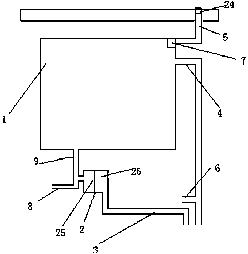
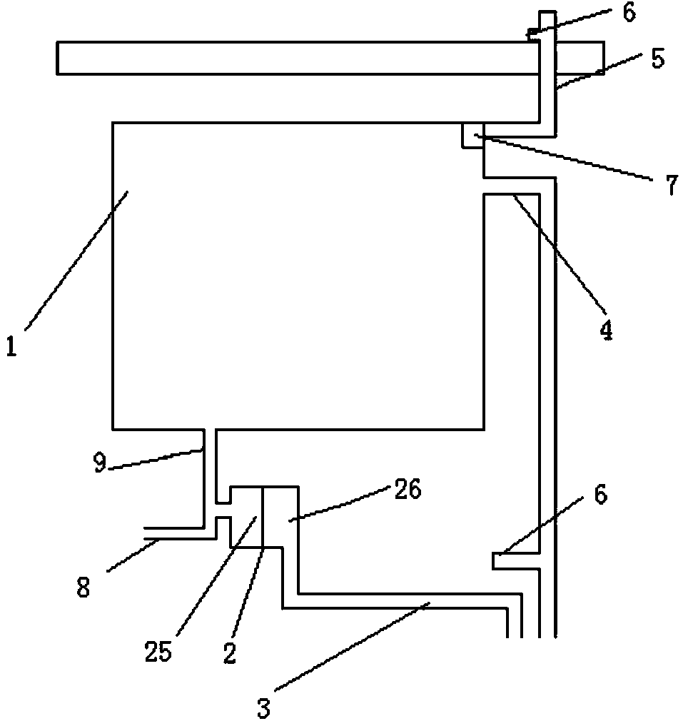
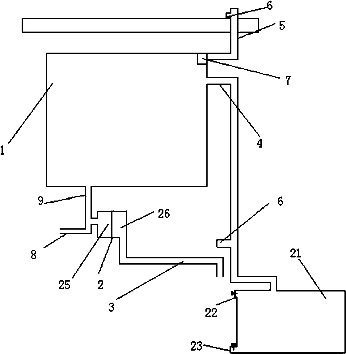
[0037]In the present invention, by dividing the original set of water resources recycling system into two sets of independent pipelines, one set of pipelines is specially used to collect and store reclaimed water, and the other set of pipelines is specially used for domestic water supply and domestic waste water discharge. The present invention makes a more reasonable improvement in the structure and material of the water resource recycling system from the overall structure, the connection mode of each pipeline, and the devices involved in the collection, storage and discharge of reclaimed water...


PUM


Abstract

The invention relates to the technical field of water recycling and provides a building reclaimed water recycling system. The building reclaimed water recycling system comprises a water storage tank, a closestool, a water inlet pipe, a braided pipe I, a braided pipe II, a sewage discharging pipe, an overflow pipe, reclaimed water pipes and a filtering device, wherein the water inlet pipe is connected with the reclaimed water pipe at the upper floor, the tail end of the water inlet pipe is connected with the top end of one side of the water storage tank, one filtering device is arranged inside the water storage tank and is arranged below the tail end of the water inlet pipe, the overflow pipe is additionally arranged below one side, close to the filtering device, of the water storage tank, the side end of the overflow pipe is connected with the reclaimed water pipe at the floor; the closestool comprises a closestool water tank and an excrement tank, an internal thread straight joint is arranged at the bottom end of the water storage tank, a three-way pipeline is arranged at a water inlet of the closestool water tank, the internal thread straight joint is connected with one opening of the three-way pipeline by virtue of the braided pipe I, the braided pipe II is connected with the other opening of the three-way pipeline, an on-off valve is arranged on each of the braided pipe I and the braided pipe II, and a water outlet of the excrement tank is connected with the sewage discharging pipe.

Description

technical field [0001] The invention relates to a reclaimed water reuse system in a building, in particular to a pipeline system for flushing toilets and irrigating plants in a residential area by collecting domestic water generated by washing machines, washbasins and bathing in the toilets in the building. Background technique [0002] About one-third of the world's people live in areas of moderate and high water scarcity, where freshwater consumption exceeds 10% of total renewable water resources. About 80 countries, 40% of the world's population experienced severe water scarcity in the mid-1990s (CSD 1997b). According to the United Nations Secretary-General's report on the comprehensive estimation of fresh water in September 1997, humans are now directly or indirectly using more than half of the world's water supply, and the global per capita fresh water availability has dropped from 17,000 cubic kilometers in 1950 to 7,000 cubic kilometers in 1995. cubic meter. By 2020...

Claims


Application Information

Patent Timeline
IPC IPC(8): E03C1/12C02F9/02
Inventor 钟孝国
Owner 钟孝国
Why Eureka
Try Eureka