Phosphorite decarburization calcination device

A calcination device and phosphate rock technology, applied in the direction of fluidized bed furnace, furnace, lighting and heating equipment, etc., can solve the problem of no energy saving, low heat recovery rate of high-temperature flue gas and high-temperature phosphate rock clinker, equipment and replacement The heat method is outdated and other problems, and the effect of high phosphorus recovery rate is achieved

Active Publication Date: 2014-06-18
成都建筑材料工业设计研究院有限公司
View PDF5 Cites 1 Cited by
  • Summary
  • Abstract
  • Description
  • Claims
  • Application Information

AI Technical Summary

Problems solved by technology

However, at present, the traditional method of producing yellow phosphorus either does not carry out pre-calcination, or even if there is pre-calcination, it is relatively backward in terms of equipment and heat exchange methods, and the heat recovery rate for high-temperature flue gas and high-temperature phosphate rock clinker is low, and there is no Realize the best conditions for saving energy and reducing consumption

Method used


Image

  • Phosphorite decarburization calcination device
  • Phosphorite decarburization calcination device
  • Phosphorite decarburization calcination device

Examples


Embodiment 1

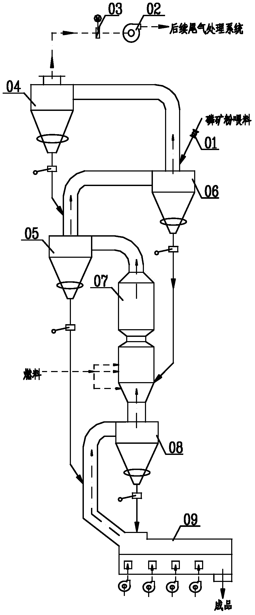
[0039] Such as figure 1 As shown, the solid line with arrows in the figure indicates the material flow, and the dotted line with arrows indicates dusty gas or gas-solid mixture. A decarbonization and calcination device for phosphate rock, including a flue gas heat recovery and phosphate rock powder preheating section, a phosphate rock powder fluidized calcination decomposition section, and a phosphate rock clinker cooling and heat recovery section connected in sequence, flue gas heat recovery and phosphorus The mineral powder preheating section is composed of connected three-stage gas-solid separators, the fluidized calcination and decomposition section of phosphate rock powder is a fluidized calciner, and the phosphate rock clinker cooling and heat recovery section is composed of connected low-speed convective heat exchangers It is composed of a first-stage gas-solid separator.

[0040] 1. High temperature flue gas heat recovery and phosphate rock powder preheating section: ...

Embodiment 2

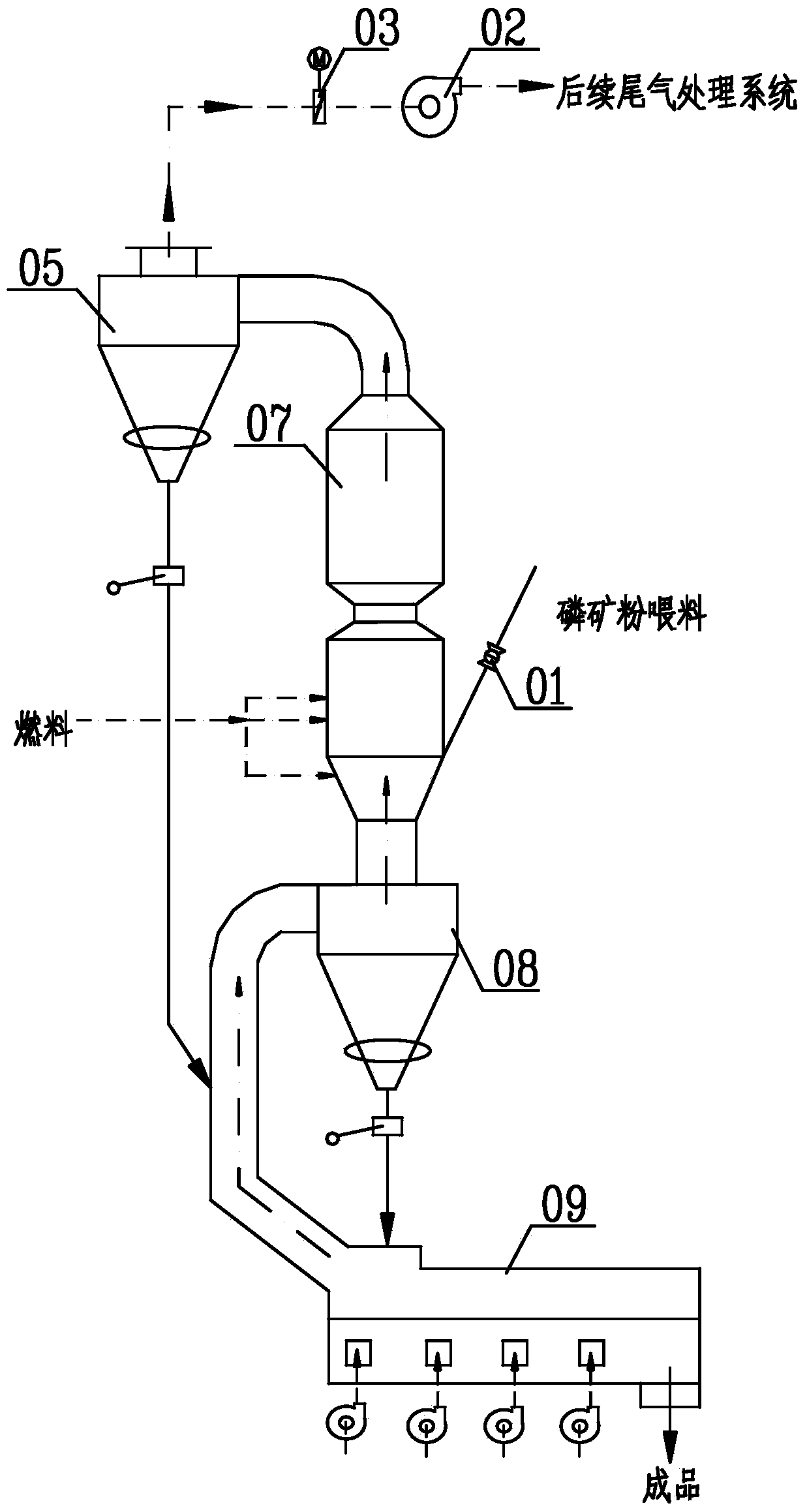
[0050] Such as figure 2 As shown, this embodiment is basically the same as Embodiment 1, the difference being that the flue gas heat recovery and phosphate rock powder preheating section is composed of a first-stage gas-solid separator. At this time, the phosphate rock powder raw material does not undergo flue gas heat recovery and The phosphate rock powder is preheated in the preheating section, and is directly put into the fluidized calciner 7 for pre-calcination, but the heat of the high-temperature phosphate rock clinker after calcination is recovered through cooling of the phosphate rock clinker and heat recovery.

Embodiment 3

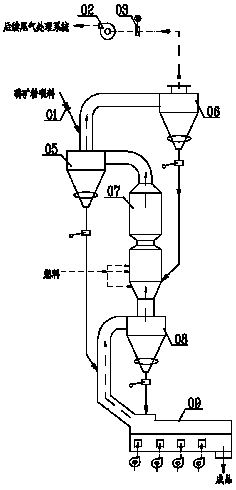
[0052] Such as image 3 As shown, this embodiment is basically the same as Embodiment 1, and the difference is that the flue gas heat recovery and phosphate rock powder preheating section is composed of two-stage gas-solid separators, and the phosphate rock powder raw material is only passed through flue gas heat recovery and rock phosphate powder preheating section. Preheating of primary suspension downstream heat exchange in the preheating section of phosphate rock powder.


PUM


Abstract

The invention discloses a phosphorite decarburization calcination device and belongs to the field of phosphorite decarburization calcination. The phosphorite decarburization calcination device comprises a flue gas heat recovering and phosphorite powder preheating section, a phosphorite powder fluidized calcination decomposition section and a phosphorite clinker cooling and heat recovery section which are sequentially communicated, wherein the flue gas heat recovering and phosphorite powder preheating section comprises at least three stages of gas-solid separators which are communicated, the phosphorite powder fluidized calcination decomposition section is a material scattering and fluidized calcination device, and the phosphorite clinker cooling and heat recovery section comprises an air cooling device and at least one stage of gas-solid separator which are communicated. The phosphorite decarburization calcination device disclosed by the invention has the advantages that the carbonate decomposition rate is high, the phosphorus recovery rate of the subsequent process can be greatly improved and the effects of energy saving and consumption reduction are remarkably realized.

Description

technical field [0001] The invention belongs to the field of decarburization and calcination of phosphate rock. Background technique [0002] The grade of phosphate rock in our country is low. Except for a few rich ores that can be used directly, most of them need to be processed to be used. Phosphate rock is a non-renewable resource. The washing and utilization of low-grade phosphate rock resources, especially the pre-calcination of low-grade phosphate rock is an effective measure to improve the phosphorus recovery rate of yellow phosphorus production, save energy and reduce consumption. The reaction of carbonate in phosphate rock is an endothermic reaction, and the presence of a large amount of carbonate will cause the temperature in the calcined yellow phosphorus furnace to drop. At the same time, the CO released after the decomposition of carbonate 2 The reaction with phosphorus steam to form low-valent oxides of phosphorus will cause loss of phosphorus and reduce the ...

Claims


Application Information

Patent Timeline
Patent Type & Authority Applications(China)
IPC IPC(8): F27B15/00F27B15/02F27B15/10F27B15/16
Inventor 蔡顺华高敏刘建文柏鸣陈军磊
Owner 成都建筑材料工业设计研究院有限公司
Why Eureka
Try Eureka