Ultrasonic plasma gun feeding powder internally

A technology of supersonic plasma and internal powder feeding, applied in the direction of plasma, electrical components, etc., can solve the problems of unstable jet flow, poor batch stability of coating quality, high cost, etc., and achieve low nozzle blocking rate and batch stability Good performance and high work efficiency

Inactive Publication Date: 2014-06-18
XI AN JIAOTONG UNIV
View PDF6 Cites 6 Cited by
  • Summary
  • Abstract
  • Description
  • Claims
  • Application Information

AI Technical Summary

Problems solved by technology

Although SAPS shows great advantages, the existing supersonic plasma spray guns still have low thermal efficiency of spray guns, low service life of nozzles and electrodes, serious nozzle clogging problems, unstable jet flow conditions, and high-quality coatings in the actual application process. Difficult to control organizational structure, low repeatability, poor batch stability of coating quality, etc.
Using process experiment to optimize the structure of the spray gun, the traditional method of designing and processing first and then optimizing the experiment also has certain blindness, low efficiency and high cost, and it is difficult to meet the development cycle of the current plasma spray gun.
Moreover, it is difficult to use experimental methods to detect the flow field characteristics inside the spray gun, and the influence of physical properties on the relationship between the structural parameters of the spray gun and the microstructure of the coating is not clear, so it is difficult to accurately evaluate the structural performance of the spray gun through experimental means.

Method used


Image

  • Ultrasonic plasma gun feeding powder internally
  • Ultrasonic plasma gun feeding powder internally
  • Ultrasonic plasma gun feeding powder internally

Examples


Embodiment Construction

[0018] The present invention will be described in further detail below in conjunction with the accompanying drawings.

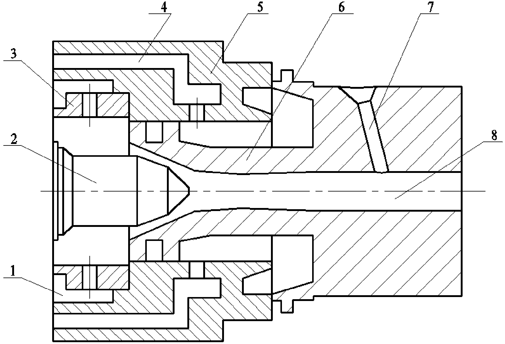
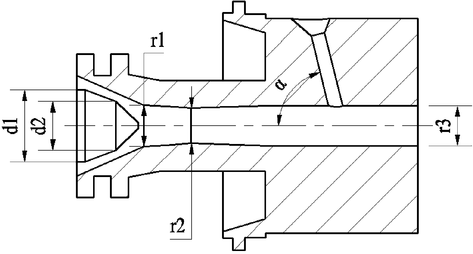
[0019] see figure 1 The present invention includes a gun body 5 and a cathode 2 installed in the gun body. The cathode 2 includes a cylindrical body and a conical front end, and one end is inserted into the gun body 5 to match the conical structure of the front end of the cathode 2. Cooperating anode 6, the anode 6 is provided with a convergent-divergent main flow channel 8, and the compression and expansion section is a Rafael curved surface, and the outer wall of the anode 6 is also provided with a delivery channel that communicates with the main flow channel 8. Powder flow channel 7, cooling water flow channel 4 and air flow channel 1 are distributed in the gun body 5, a gas distribution ring 3 is installed in the air flow channel 1, and an air inlet connected to the main air flow channel 8 is provided on the gas distribution ring 3 .

[0020] The conica...


PUM


Abstract

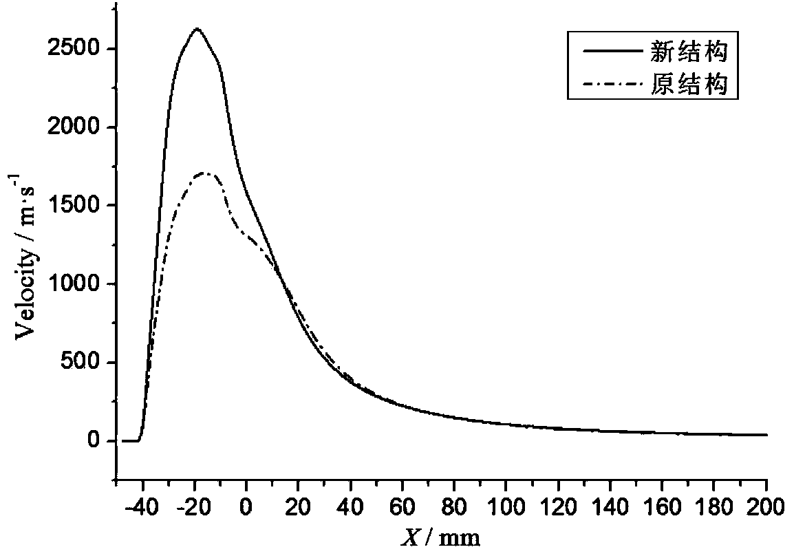
The invention discloses an ultrasonic plasma gun feeding powder internally, which is designed by adopting a parameterized structure design method in combination with a numerical simulation technique. The ultrasonic plasma gun mainly comprises a cathode, an anode, a powder feeding air flow channel, and a main air flow channel formed by matching the cathode with the anode. The mechanical compression effect of a nozzle is adjusted by changing the parameter of each pore canal in the internal compression segment and expanding segment of an anode nozzle, so that plasma jet flow in the gun is high in energy density and speed, the thermal efficiency of the gun is increased, and meanwhile the stability of arc voltage is ensured. The internal powder feeding angle is changed to an optimal position, so that heating and acceleration of sprayed powder materials are facilitated, and the problem of blocking of the gun nozzle is solved. The size of the gun is selected on the basis of an advanced computer simulation technology, so that the development period of the gun is shortened greatly, and the design cost is lowered. As proved by results, the novel gun has higher flow field characteristic than an original structure.

Description

technical field [0001] The invention relates to a spraying equipment, in particular to an internal powder feeding supersonic plasma spray gun. Background technique [0002] Supersonic plasma spraying (SAPS) refers to the high energy density and extended extended plasma arc obtained by further compressing and accelerating the high-pressure and high-speed plasma gas on the basis of the traditional non-transferred plasma arc, which can obtain several times the speed of sound A method of spraying with a supersonic plasma jet. Compared with ordinary plasma spraying (spraying particle speed is about 200-400m / s), the high energy density of supersonic plasma jet can instantly melt high-melting point spraying materials, and can quickly accelerate the molten particles to break through the sound barrier to 450-900m / s supersonic level. Studies have shown that thermal shock performance, heat insulation performance and high temperature oxidation of thermal barrier coatings prepared by s...

Claims


Application Information

Patent Timeline
Patent Type & Authority Applications(China)
IPC IPC(8): H05H1/42
Inventor 魏正英谭超魏培杜军
Owner XI AN JIAOTONG UNIV
Why Eureka
Try Eureka