An automatic magnetic anti-rotation slag fishing machine for swirl wells

A swirling well and anti-rotation technology, which is applied to the feeding/discharging device of the settling tank, and the separation of sediments by centrifugal force, etc., can solve the problem of increasing the difficulty of cleaning scale, wasting time, manpower and material resources, and working environment sanitation Very bad and other problems, to achieve the effect of improving efficiency, increasing adsorption capacity, and high work efficiency

Active Publication Date: 2015-09-09
青岛正大正电力环保设备有限公司
View PDF5 Cites 0 Cited by
  • Summary
  • Abstract
  • Description
  • Claims
  • Application Information

AI Technical Summary

Problems solved by technology

[0004] The problem of iron scale cleaning in swirl wells has always been a bottleneck restricting production. The usual method is to accumulate the scale at the bottom of the swirl well after a certain period of time and then grab it out of the well with a slag grabber and return it to the steelmaking process for recycling. The whole process requires a lot of manpower to complete. This traditional method of iron scale cleaning not only wastes a lot of time, manpower and material resources, but also has a very bad impact on the sanitation of the working environment.
[0005] In addition, the cooling water entering the swirl well is in a state of high-speed rotation. When using a conventional grab to clean the scale at the bottom of the swirl well, when the grab enters the water surface, the grab rotates synchronously with the water flow in the swirl well, causing the crane to The torsion of the steel wire rope increases the difficulty of cleaning the scale. Therefore, how to effectively avoid the torsion problem in the process of cleaning and transporting the scale needs to be solved urgently

Method used


Image

  • An automatic magnetic anti-rotation slag fishing machine for swirl wells

Examples


Embodiment Construction

[0028] The present invention will be described in detail below in conjunction with the accompanying drawings, so that those of ordinary skill in the art can implement it after referring to this specification.

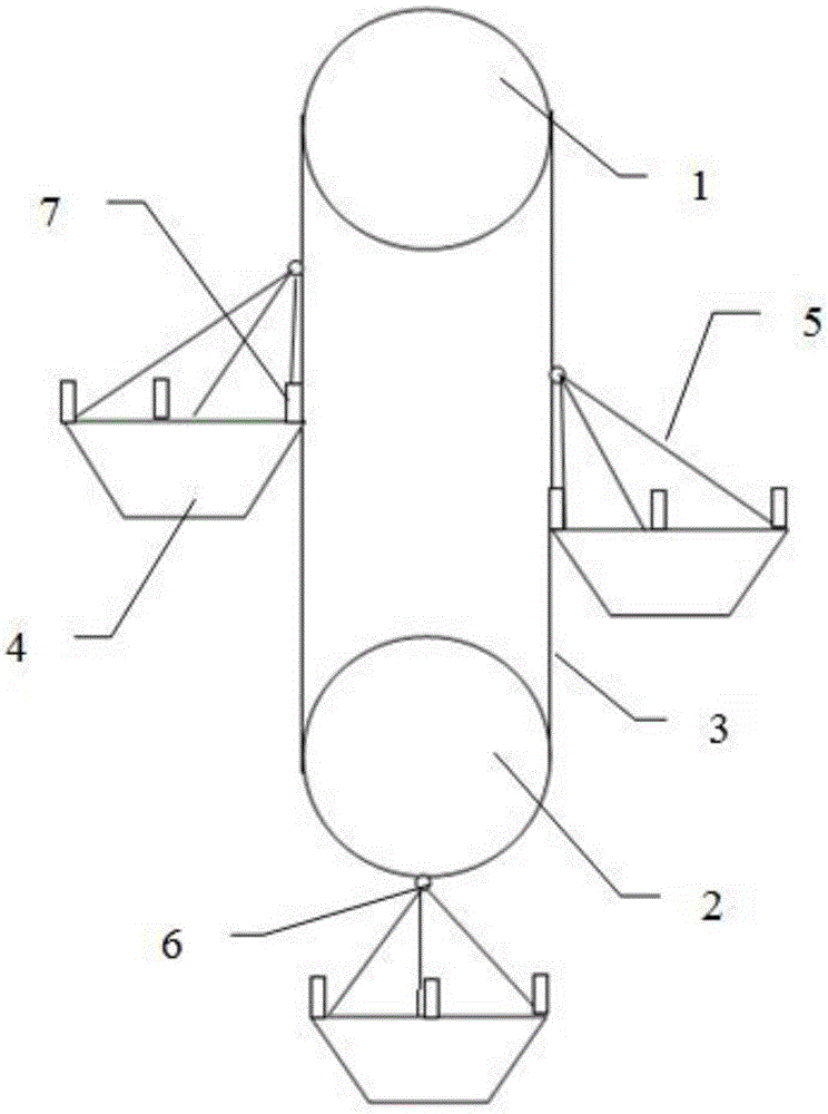
[0029] Such as figure 1 As shown, an automatic magnetic anti-rotation slag removal machine for a swirl well according to the present invention includes:

[0030] The transmission mechanism includes a rotating wheel and a transmission belt 3, and the rotating wheel includes a first rotating wheel 1 and a second rotating wheel 2, and the first rotating wheel 1 and the second rotating wheel 2 are arranged longitudinally and have a certain interval, so The rotating wheel is connected with a motor and is driven to rotate, and the transmission belt 3 is wound around the outside of the first rotating wheel 1 and the second rotating wheel 2 and is driven to rotate by the rotating wheel, forming a longitudinally running through the rotating wheel. Transmission mechanism inside ...


PUM

PropertyMeasurementUnit
lengthaaaaaaaaaa
diameteraaaaaaaaaa

Abstract

The invention discloses an automatic magnetic anti-rotation slag salvaging machine for a whirling well. The automatic magnetic anti-rotation slag salvaging machine comprises a conveyance mechanism and a slag salvaging mechanism, wherein the conveyance mechanism comprises rotating wheels and a conveyor belt, and the rotating wheels comprise a first rotating wheel and a second rotating wheel, and the conveyor belt is wound around the exteriors of the first rotating wheel and the second rotating wheel and is driven by the rotating wheels to rotate; the slag salvaging mechanism is formed by a plurality of conical slots, an opening is formed in the top of each conical slot, the sidewall and bottom of each conical slot are latticed and are formed by hollow tubes with magnetism conduction capability, the surface of each hollow tube is provided with a plurality of bulges for increasing the surface area of each hollow tube, the conical slots are connected with the conveyor belt and are driven by the conveyor belt to rotate, the conical slots are connected with the conveyor belt through hinges, and an alternating current coil capable of generating magnetic force is arranged in each hollow tube forming the conical slots; the sidewall of each conical slot is provided with a first groove, and the conveyor belt is provided with protruded strips matched with the first grooves at positions corresponding to the conical slots.

Description

technical field [0001] The invention relates to the technical field of steel rolling wastewater treatment, in particular to an automatic magnetic anti-rotation slag removal machine for swirl wells. Background technique [0002] In the process of steel rolling, the rolling mill bearings, rolls, etc. need to be cooled by water, and the iron sheet groove needs to be washed by water. The used water contains a large amount of iron oxide scale. For every ton of steel smelted, more than 17 kg of iron oxide scale is produced. These oxide scales are absolutely Most of them enter the water, making the content of suspended solids in the water as high as several thousand mg / L. Therefore, the cooling water can not only be used directly, but also cannot be discharged directly according to environmental protection requirements. Therefore, the steel rolling system needs water treatment and circulation facilities. [0003] The swirl well is a vortex type sedimentation tank, which is widely ...

Claims


Application Information

Patent Timeline
Patent Type & Authority Patents(China)
IPC IPC(8): B01D21/26B01D21/24
Inventor 吴燕妮
Owner 青岛正大正电力环保设备有限公司
Why Eureka
Try Eureka