
Pay-off cylinder support

A technology of No. 1, side plate, applied in the direction of conveying filamentous materials, thin material handling, transportation and packaging, etc., can solve the problems of dust contamination, reduced conductor elongation, broken wires, etc., to reduce materials and man-hours, structure Reasonable design and small footprint effect

Inactive Publication Date: 2014-06-25
ANHUI YASHEN CABLE GRP
View PDF5 Cites 1 Cited by
  • Summary
  • Abstract
  • Description
  • Claims
  • Application Information

AI Technical Summary

Problems solved by technology

[0003] During the processing and extrusion production of cables and other conductors, due to the gravity of the conductor on the pay-off reel and the traction and expansion force in the process of processing, it is very easy to generate internal stress due to stretching, resulting in a decrease in the elongation of the conductor and the phenomenon that the conductor is thinned. , severe and even broken wires
[0004] At present, this type of support is mainly a thimble shaft type ground pay-off frame, and its main supporting principle is: the pay-off cylinder is placed on two conical blocks, and the conical block at one end is fixed on the screw that controls the left and right movement of the pay-off cylinder , the other end of the lead screw is connected with a device for adjusting the height of the lead screw, and the tapered block at the other end is supported by the cantilever structure. The disadvantage of this type of bracket is: since the tapered block at one end is supported by the cantilever structure, the moment on the cantilever is relatively large. Large, long-time loading of the pay-off tube makes the cantilever very easy to fail. In addition, the connection between the tapered block and the pay-off tube adopts a bearing structure, which makes the pay-off tube easy to rotate. However, once the wire breaks or the machine stops, due to The inertia effect pay-off drum will still rotate for a long time, which will cause the metal wire to scatter on the ground and be contaminated with dust, which is not conducive to the subsequent use of the metal wire, and the pay-off drum is generally small in size, and the thimble shaft type ground pay-off frame is used to occupy A larger space is not conducive to movement, and the tension is large, and the metal wire is prone to be thinned and broken.

Method used


Image

  • Pay-off cylinder support
  • Pay-off cylinder support
  • Pay-off cylinder support

Examples


Embodiment Construction

[0016] In order to make the technical means, creative features, goals and effects achieved by the present invention easy to understand, the present invention will be further described below in conjunction with specific illustrations.

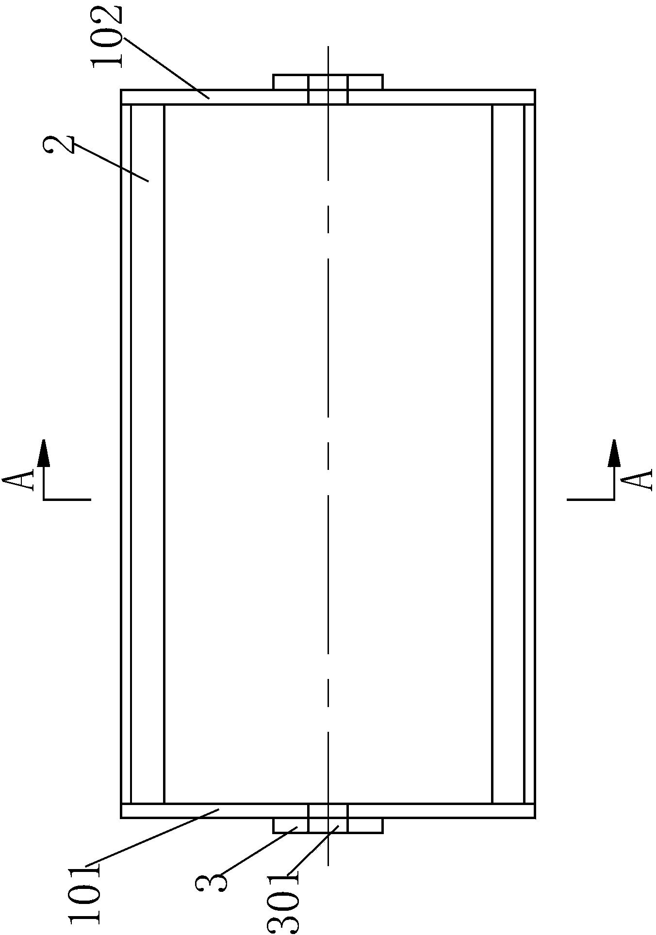
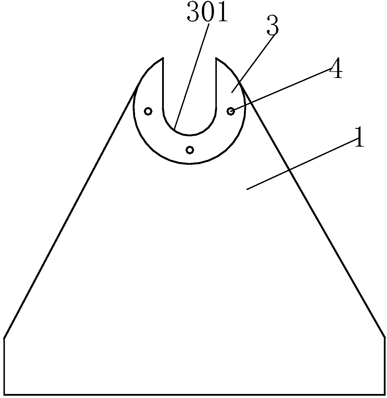
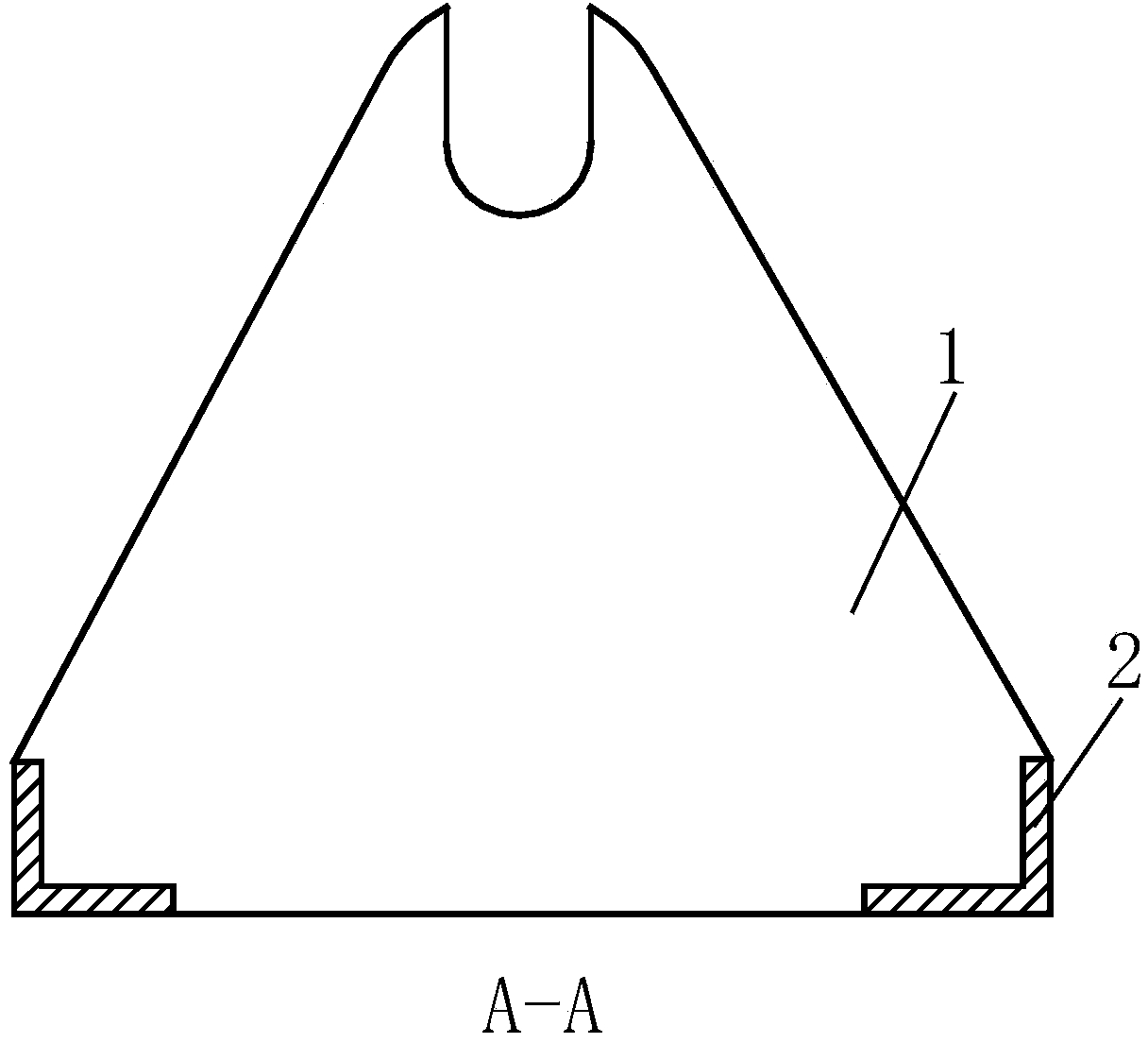
[0017] like Figure 1 to Figure 4 As shown, a pay-off barrel support includes No. 1 side plate 101 and No. 2 side plate 102 supported on both sides of the pay-off barrel 5. The top left side of the No. 1 side plate 101 is fixed by riveting Grinding copper alloy bearing bush 3, the top of the No. 1 side plate 101 is provided with a groove 301 to facilitate the support of the extension shaft 6 on the pay-off barrel 5, and the left and right sides of the No. 1 side plate 101 are sloped to reduce the The use of materials; the top of the copper alloy bearing bush 3 is provided with the same groove 301 as the groove 301 at the top of the No. 1 side plate 101, so that the copper alloy bearing bush 3 and the No. 1 side plate 101 jointly support the pay-...


PUM


Abstract

The invention relates to a pay-off cylinder support. The pay-off cylinder support comprises a first side plate and a second side plate. A copper alloy baring pad is fixed to the top end of the left side of the first side plate in a rivet mode. A groove is formed in the top end of the first side plate. Both the left lateral side and the right lateral side of the first side plate are slopes. A groove which is the same as the groove in the top end of the first side plate is formed in the top end of the copper alloy bearing pad. The second side plate and the first side plate are symmetrically arranged, and a beam is arranged between the second side plate and the first side plate. The pay-off cylinder support has the advantages of being reasonable in structural design, low in cost, light in weight, convenient to move, small in size, small in occupied space and the like. The grooves in the front ends of the first side plate and the second side plate make direct contact with extending shafts at the two ends of the pay-off cylinder, pay-off tension force is controlled through sliding friction force of the extending shafts on the copper alloy bearing pad, instant stopping can be achieved when hard shutdown occurs in high-speed and low-speed production processes, no phenomena of much pay-off and thread collection can be generated, and material waste and work hour waste are reduced.

Description

technical field [0001] The invention relates to the technical field of bracket equipment, in particular to a cable pay-off drum bracket. Background technique [0002] In the manufacturing process of cables, there is a process of wrapping a layer of insulation around the cable wires. The cable wires are generally copper wires or aluminum wires. These metal wires are wound on the pay-off barrel before wrapping the insulation layer. The pay-off spool is supported by a bracket. The metal wire is released from the pay-off barrel under the action of pulling, and drives the pay-off barrel to rotate on the support at the same time. [0003] During the processing and extrusion production of cables and other conductors, due to the gravity of the conductor on the pay-off reel and the traction and expansion force in the process of processing, it is very easy to generate internal stress due to stretching, resulting in a decrease in the elongation of the conductor and the phenomenon that...

Claims


Application Information

Patent Timeline
Patent Type & Authority Applications(China)
IPC IPC(8): B65H49/20
Inventor 胡宏权
Owner ANHUI YASHEN CABLE GRP
Learn More