Bridge floor crane for cable-stayed bridge

A cable-stayed bridge and crane technology, which is applied to walking bridge cranes, bridges, cranes, etc., can solve the problems of overturning and instability of cranes, limited lifting height and lifting weight, and hidden dangers, so as to avoid potential safety hazards. , The effect of avoiding the instability of lifting and dispersing the construction load

Inactive Publication Date: 2014-06-25
CHONGQING CONSTR BRIDGE ENG +2
View PDF7 Cites 15 Cited by
  • Summary
  • Abstract
  • Description
  • Claims
  • Application Information

AI Technical Summary

Problems solved by technology

Because the cable-stayed bridge has the advantages of large span and strong pressure, it is developing more and more rapidly in China at present, and the types of cranes used in the installation and construction of the steel girder of the cable-stayed bridge mainly include floating crane and cable-loaded crane. The disadvantages of machine hoisting and floating hoisting are that the hoisting height and hoisting weight are limited, which cannot meet the construction requirements of large-span cable-stayed bridges at the present stage; and for the hoisting of heavy steel truss girders, hydraulic hoisting spanning cable hoisting is mostly used. machine, the advantages are stable lifting and large lifting tonnage, but at the same time there is also the problem of high cost, which is not suitable for large-scale promotion and application
In addition, the traditional bridge deck crane still has the following disadvantages: the stability of the crane is poor during the walking process, the front cantilever is too long, and the heavy lifting gravity causes the crane to overturn and become unstable, which affects the construction efficiency; the safety facilities are not in place, and when the crane When an unstable state occurs, the backup safety device cannot take effect in time, and there is a great potential safety hazard

Method used


Image

  • Bridge floor crane for cable-stayed bridge
  • Bridge floor crane for cable-stayed bridge
  • Bridge floor crane for cable-stayed bridge

Examples


Embodiment Construction

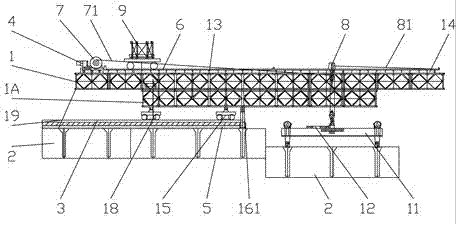
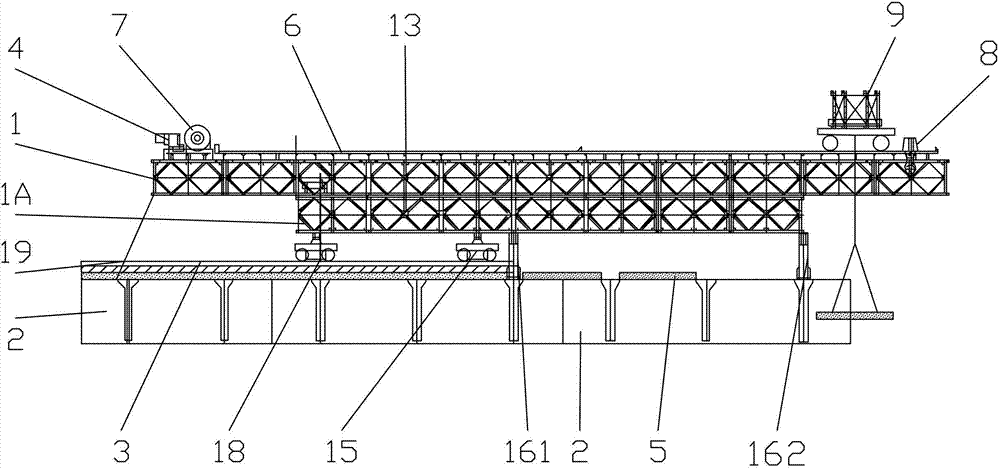
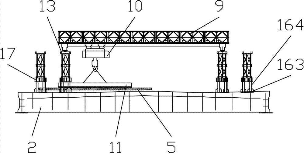
[0023] Below in conjunction with accompanying drawing and embodiment the technical solution of the present invention is further described:

[0024] Such as Figure 1 to Figure 6As shown, the present invention provides a cable-stayed bridge deck crane, comprising two sets of oppositely arranged main trusses 1, a hoisting system located above the main truss 1, and a walking system located below the main truss 1, the walking system comprising The main track 3 laid on the installed steel girder 2 and the running device slidingly matched with the main track 3, wherein the main truss 1 adopts an upper and lower two-layer structure, and also includes a support system arranged at the lower part of the main truss 1, which is located on the two Set the rear anchoring system on the outside of the main truss 1, the counterweight device 4 and the safety device arranged at the rear end of the main truss 1, and the support system includes the middle support device 161 arranged in the middle ...


PUM


Abstract

The invention relates to a construction device for a cable-stayed bridge, in particular to a bridge floor crane for the cable-stayed bridge. The bridge floor crane for the cable-stayed bridge comprises two sets of main trusses arranged oppositely, a craning system arranged above the main trusses and a walking system arranged below the main trusses, wherein the walking system comprises a main track laid on a mounted steel beam and a walking device in sliding fit with the main track, and an upper layer and lower layer structure is adopted by the main trusses. The bridge floor crane for the cable-stayed bridge further comprises a supporting system arranged on the lower portions of the main trusses, a rear anchoring system arranged on the outer sides of the two sets of the main trusses, a balance weight device and a safety device, the balance weight device and the safety device are arranged at the rear ends of the main trusses, and the supporting system comprises a middle supporting device arranged in the middles of the main trusses and a temporary supporting device arranged at the front ends of the main trusses. Through the adoption of the technical scheme, the bridge floor crane for the cable-stayed bridge has the advantages of being proper in craning height, strong in bearing capacity, good in construction stability, high in construction efficiency and high in safety.

Description

technical field [0001] The invention relates to a cable-stayed bridge construction device, in particular to a cable-stayed bridge deck crane. Background technique [0002] Cable-stayed bridge is a kind of bridge in which the main girder is directly pulled on the bridge tower by many cables. The multi-span elastically supported continuous beam with cables instead of buttresses can reduce the bending moment in the beam body, reduce the building height, reduce the structural weight, and save materials. Because the cable-stayed bridge has the advantages of large span and strong pressure, it is developing more and more rapidly in China at present, and the types of cranes used in the installation and construction of the steel girder of the cable-stayed bridge mainly include floating crane and cable-loaded crane. The disadvantages of machine hoisting and floating hoisting are that the hoisting height and hoisting weight are limited, which cannot meet the construction requirements ...

Claims


Application Information

Patent Timeline
Patent Type & Authority Applications(China)
IPC IPC(8): E01D21/00B66C17/04B66C5/02B66C7/08B66C9/08
Inventor 张天许贾定强
Owner CHONGQING CONSTR BRIDGE ENG
Why Eureka
Try Eureka