A shunt linear isolation circuit and its oscilloscope

A technology of isolating circuits and routing, applied in the direction of voltage/current isolation, instruments, measuring electrical variables, etc., can solve the problems of complex low-frequency path circuits, increase high-frequency, low-pass, etc., and achieve simple circuit form and high DC accuracy Effect

Active Publication Date: 2017-10-24
RIGOL
View PDF4 Cites 0 Cited by
  • Summary
  • Abstract
  • Description
  • Claims
  • Application Information

AI Technical Summary

Problems solved by technology

[0012] 1. Since the secondary side of the transformer uses two windings, as the positive and negative poles of the output differential signal, it is difficult to ensure the same phase of the positive and negative poles, which increases the difficulty of transformer winding
[0013] 2. The linear optocoupler is used as the isolation of the low-frequency path. The delay of the low-frequency path causes the frequency response to be uneven. Circuits 48, 52, 50, and 54 are used to compensate. Because the capacitors are discrete, it is difficult to ensure that the positive and negative poles of the differential signal are completely unanimous
[0024] 2. The delay compensation circuit 103 or 22, 24, 29, 30 mentioned in the patent cannot actually solve the amplitude-frequency sag at the overlapping frequency of the low-frequency and high-frequency paths
Because the capacitors 24 and 30 play a low-pass role in the amplifier circuit shown, they can only make the high frequency of the low frequency path lower than the low frequency, but cannot properly increase the high frequency.
Circuit 103 is actually an RC low-pass circuit, which also cannot properly enhance high frequencies.
[0025] 3. Since the provided delay compensation circuit does not work, the output amplitude-frequency response of the linear isolation circuit is not flat
[0026] 4. The low-frequency path circuit is complex
[0027] To sum up, the main disadvantage of the existing technology is that the bandwidth of the linear isolation circuit that can be realized is low, and the isolation oscilloscope with a larger bandwidth cannot be realized.
Moreover, the frequency response depression problem caused by the linear optocoupler circuit

Method used


Image

  • A shunt linear isolation circuit and its oscilloscope
  • A shunt linear isolation circuit and its oscilloscope
  • A shunt linear isolation circuit and its oscilloscope

Examples


Embodiment 1

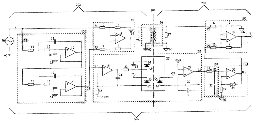
[0103] Figure 6 It is the structural diagram of this embodiment. This embodiment is used to realize linear isolation for single-ended signal input.

[0104] In this embodiment, the low-frequency amplifying circuit amplifier U1 selects a low-bandwidth high-precision amplifier, and the circuit form of the low-frequency amplifying circuit can have the following four forms:

[0105] As shown in Figure 7(A), form 1 follows the circuit, and the circuit bandwidth is determined by the amplifier itself.

[0106] As shown in Figure 7(B), Form 2 is a low-pass follower circuit, and the circuit bandwidth is determined by R1, C1 and the amplifier bandwidth.

[0107] As shown in Figure 7(C), form 3, RC low-pass first, and then the amplifier follows, the circuit bandwidth is determined by R, C and the amplifier bandwidth.

[0108] As shown in Figure 7(D), Form 4 is an active second-order low-pass amplifier. The circuit bandwidth is determined by R1, C1, R2, C2 and the amplifier bandwidth....

Embodiment 2

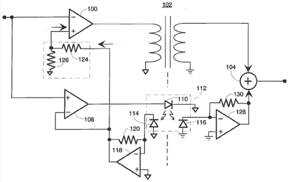
[0128] Figure 9 It is the structural diagram of this embodiment.

[0129] The difference between the second embodiment and the first embodiment is that both the driving and receiving of the transformer T1 adopt a differential mode. The amplifier of the high-frequency subtraction amplifier circuit is a fully differential amplifier, and the output of the amplifier is a differential signal, which is connected to both ends of the primary side of the transformer T1 to drive the transformer. The signal input and the low-frequency signal are connected to the two input terminals of the differential amplifier circuit to form a subtraction circuit. Resistance value R2=R3=R4=R5=300Ω.

[0130] The snubber circuit is connected as Figure 9 As shown, the transformer load resistor R6 is connected to both ends of the secondary side of the transformer, and connected to the positive and negative input terminals of the differential amplifier circuit.

Embodiment 3

[0132] Figure 10 This is the structure diagram of the branch linear isolation circuit in this embodiment.

[0133] This embodiment provides a shunt linear isolation circuit for differential signal input. The signal input is a differential signal, and the low-frequency amplifier circuit also adopts a fully differential amplifier circuit. Its bandwidth can be selected according to the requirements of the low-frequency path, and an additional low-pass filter circuit can also be added to ensure that the bandwidth of the low-frequency path meets the signal input requirements of the Σ-ΔADC. . Such as ADI's fully differential amplifier AD8476.

[0134] Or use two single-ended amplifiers to amplify the P and N terminals of the differential input signal at low frequencies respectively, and the selection of the amplifiers is the same as in Embodiment 1, such as Figure 11 shown.

[0135] The difference between the high-frequency subtraction amplifier circuit and Embodiment 2 is tha...


PUM


Abstract

The invention provides a shunt linear isolation circuit, which can be applied to measuring equipment such as an oscilloscope, including: a low-frequency amplifier circuit, a first analog-to-digital converter, a digital isolator, a high-frequency subtraction amplifier circuit, a transformer, and a second analog-to-digital converter And the control processing circuit uses the low-frequency amplifier circuit and the high-frequency subtraction amplifier circuit to decompose the input signal into a DC-to-low-frequency part and a low-frequency-to-high-frequency part, wherein the low-frequency part is sampled by the first analog-to-digital converter and then passed through a digital isolation device The output to the control processing circuit expands the selection range of the isolator in the low-frequency path due to the adoption of sampling first and then isolation; the high-frequency part is isolated by a transformer and then sampled and output to the control processing circuit through the second analog-to-digital converter , realizing the high sampling rate and high bandwidth of the oscilloscope. The shunt linear isolation circuit can be conveniently applied to measuring equipment such as an oscilloscope.

Description

technical field [0001] The invention relates to electronic measuring equipment, in particular to a shunt linear isolation circuit and an oscilloscope thereof. Background technique [0002] The isolation circuit can transmit the electrical signal on the input side to the output side, but the input side and the output side are electrically isolated, or insulated, and there is only a small capacitance between the input side and the output side. The isolation circuit can improve the common mode rejection ratio during measurement, reduce interference, improve signal quality, and can also isolate dangerous voltages to protect equipment and personal safety. When multi-channel oscilloscopes measure at the same time, channel isolation can also measure multiple signals with different common-mode voltages to prevent short-circuit accidents caused by common ground between channels. [0003] From the frequency response of the processed signal and the isolation circuit, the isolation cir...

Claims


Application Information

Patent Timeline
Patent Type & Authority Patents(China)
IPC IPC(8): G01R15/18G01R13/00
Inventor 史慧严波王悦王铁军李维森
Owner RIGOL
Why Eureka
Try Eureka