Light emitting device and related projection system

A light-emitting device and excitation light technology, applied in projection devices, lighting devices, gas/waterproof devices, etc., can solve the problems of burning out the color wheel and increasing the temperature of the color wheel, and achieve lower working temperature, dust-proof working temperature, The effect of effectively reducing the working temperature

Active Publication Date: 2014-06-25
APPOTRONICS CORP LTD
View PDF9 Cites 26 Cited by
  • Summary
  • Abstract
  • Description
  • Claims
  • Application Information

AI Technical Summary

Problems solved by technology

Although the color wheel is exposed to the air and can conduct heat to the air to reduce the working temperature, but because there are a lot of dust particles in the air, when there are dust particles attac

Method used


Image

  • Light emitting device and related projection system
  • Light emitting device and related projection system
  • Light emitting device and related projection system

Examples


Embodiment 1

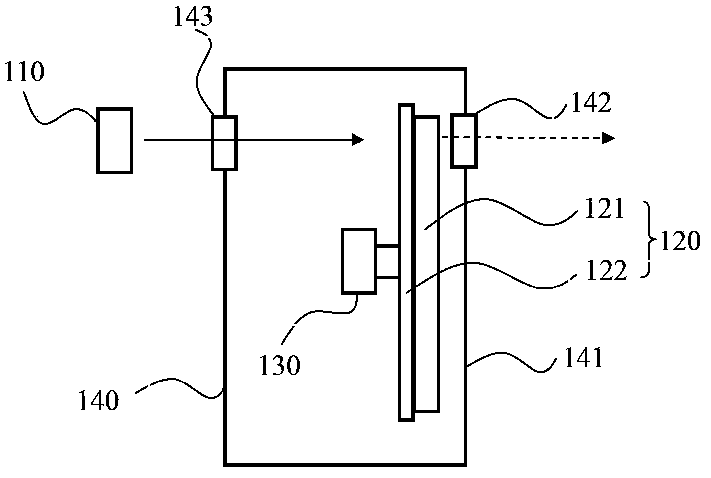
[0028] figure 1 It is a structural schematic diagram of an embodiment of the light-emitting device of the present invention, such as figure 1 As shown, the light emitting device includes an excitation light source 110 , a wavelength converting device 120 , a driving device 130 , and a sealing device 140 .

[0029] The excitation light source 110 is specifically a laser light source, which can generate laser light as excitation light for exciting the wavelength conversion material. Certainly, in other embodiments of the present invention, the excitation light source 110 may also be an LED light source or the like.

[0030] The wavelength conversion device 120 includes a wavelength conversion layer 121 . The wavelength conversion layer 121 is provided with a wavelength conversion material, which can absorb the excitation light emitted by the light source 110 and emit the received light. The wavelength conversion material in this embodiment is specifically phosphor powder. In ...

Embodiment 2

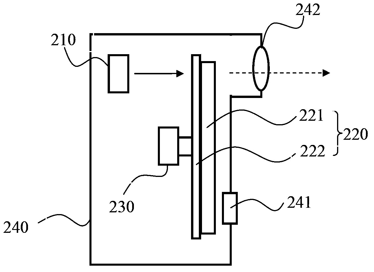
[0045] image 3 It is a structural schematic diagram of another embodiment of the light-emitting device of the present invention, such as image 3 As shown, the light emitting device includes an excitation light source 210 , a wavelength converting device 220 , a driving device 230 , and a sealing device 240 . The wavelength conversion device 220 includes a wavelength conversion layer 221 and a substrate 222 . The sealing device 240 includes a heat conduction area 241 and a light transmission area 242 .

[0046] The light emitting device of this embodiment and figure 1 The lighting devices shown differ in that:

[0047] (1) The area of ​​the heat conduction area 241 in this embodiment is relatively small, and its area is equal to the area of ​​the light spot. At this time, the heat conduction to the wavelength conversion device 220 can still be ensured, and at the same time, only the surface of the heat conduction area 241 needs to be processed so that Its flatness is high...

Embodiment 3

[0051] Figure 4 It is a structural schematic diagram of another embodiment of the light-emitting device of the present invention, such as Figure 4 As shown, the light emitting device includes an excitation light source 310 , a wavelength converting device 320 , a driving device 330 , and a sealing device 340 . The wavelength conversion device 320 includes a wavelength conversion layer 321 and a substrate 322 . The sealing device 340 includes a heat conduction area 341 and a light transmission area 342 .

[0052] The light emitting device in this embodiment and figure 1 The lighting devices shown differ in that:

[0053] (1) The wavelength conversion device 320 is a reflective color wheel, and the surface of the substrate 322 is provided with a reflective layer. The reflective layer is provided on the side of the substrate 322 close to the wavelength conversion layer 321 and can reflect the outgoing light incident on the reflective layer. The excitation light is transmitt...


PUM


Abstract

The inventiondiscloses a light emitting device and a related projection system. The light emitting device comprises an excitation light source used for generating excitation light, a wavelength conversion device comprising a wavelength conversion layer, a driving device and a sealing device, wherein the wavelength conversion layer absorbs the excitation light and emits excited light, the driving device drives the wavelength conversion layer to realize periodic rotation to enable an incident light spot in the wavelength conversion layer to do motion in the predetermined circle locus, a line speed of at least a partial region of the wavelength conversion device is greater than or equal to 75m/s, the sealing device comprises a light penetration region and a heat conduction region, the wavelength conversion device is arranged in the sealing device, the emitting light of the wavelength conversion device penetrates through the light penetration region, a distance between the heat conduction region and a light emitting face of the wavelength conversion device or an opposite surface is smaller than or equal to 1mm, heat is conducted outside the sealing device, and the area of the heat conduction region is greater than or equal to the area of the incident light spot of the excitation light. The light emitting device having a dust-proof function and a function of effective work temperature reduction of the wavelength conversion device, and the related projection system are provided.

Description

technical field [0001] The invention relates to the technical field of illumination and display, in particular to a light emitting device and a related projection system. Background technique [0002] Using colored light generated by exciting phosphors as a light source is a solution widely used in projection display and other fields. Generally speaking, the phosphor will be set on a high-speed rotating color wheel. Exciting light such as laser light is incident on the color wheel and excites the phosphor to generate the stimulated light. At the same time, a large amount of heat is generated. The high-speed rotation of the color wheel is to make different areas The phosphor powder will be exposed to the excitation light in turn, and different regions can share the heat, thereby reducing the temperature of the color wheel. [0003] Since the conversion efficiency of the phosphor powder to the excitation light is not 100%, the phosphor powder will generate a lot of heat, and ...

Claims


Application Information

Patent Timeline
IPC IPC(8): G03B21/20G03B21/00F21V9/10F21V29/00F21V31/00F21V9/40F21V29/51F21V29/67
Inventor 曹亮亮胡飞
Owner APPOTRONICS CORP LTD
Why Eureka
Try Eureka