
Hybrid type flux coupling superconduction fault current limiter and current limitation method

A fault current limiter, magnetic flux coupling technology, applied in the usage of superconductor elements, emergency protection circuit devices for limiting overcurrent/overvoltage, electrical components, etc. To solve the problems of large capital, etc., to achieve the effect of improving system economy, reducing AC loss, and responding quickly

Inactive Publication Date: 2014-06-25
WUHAN UNIV
View PDF6 Cites 7 Cited by
  • Summary
  • Abstract
  • Description
  • Claims
  • Application Information

AI Technical Summary

Problems solved by technology

At present, although some foreign manufacturers can produce circuit breakers with a breaking current of 80kA, the actual number of them used is very small, and it is difficult to guarantee safety and reliability; second, increasing the breaking capacity also means that the cost of equipment will increase. The cost of the circuit breaker is about 1.8 times that of a 63kA circuit breaker, and it will also involve the transformation or replacement of other existing auxiliary equipment, and the total investment will be relatively large
A large number of equipment transformations will also affect production operations, and the resulting economic losses are also very considerable

Method used


Image

  • Hybrid type flux coupling superconduction fault current limiter and current limitation method
  • Hybrid type flux coupling superconduction fault current limiter and current limitation method
  • Hybrid type flux coupling superconduction fault current limiter and current limitation method

Examples


Embodiment

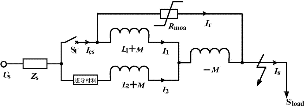
[0023] Depend on figure 1 As shown, the present invention mainly realizes the inductive-resistive hybrid current-limiting operation by controlling the closed state of the fast switch, based on the magnetic flux cancellation (locking) characteristics and the conversion of the low-high resistance state of the superconducting material.

[0024] The invention includes a coupling transformer, a fast switch connected in series with the primary side winding coil of the coupling transformer, an MOA zinc oxide resistance sheet connected in parallel on the primary side winding coil of the coupling transformer, and a superconducting limiter connected in series with the secondary side winding coil of the coupling transformer. flow material; the primary and secondary side winding coils of the coupling transformer are connected in antiparallel and then connected to the main circuit of the power system.

[0025] Among them, the material of the primary side winding coil and the secondary side...


PUM


Abstract

The invention relates to a hybrid type flux coupling superconduction fault current limiter and current limitation method. According to the hybrid type flux coupling superconduction fault current limiter, a primary side winding coil of a coupling transformer and a high-speed switch are connected and are connected into an MOA zinc oxide resistor disc, a secondary side winding coil is connected with a superconduction current limiting material in series, and then the primary side winding coil and the secondary primary side winding coil are connected in an anti-parallel mode and then are connected into a main loop of a power system. When the power system operates normally, the high-speed switch is switched on; when the power system short-circuits, the high-speed switch is controlled to be triggered and switched off, the flux locking characteristic of the coupling transformer is relieved, the superconduction material is switched to be at the high resistance state as the through-flow of the superconduction material is larger than a set critical current, and at the moment, the current limiter carries out fault current limitation in an inductance-resistance hybrid mode. The hybrid type flux coupling superconduction fault current limiter is simple in structure and rapid in response, exchange losses generated when the superconduction current limiting material operates normally are reduced, and system economical efficiency of current limiting equipment is improved.

Description

technical field [0001] The invention relates to the field of power system and automation, in particular to a hybrid magnetic flux coupling superconducting fault current limiter and a current limiting method. Background technique [0002] With the prosperity of the society and the progress of the economy, the electric power industry, which is the basic industry of the country, is also developing rapidly. Unit capacity, power plant capacity, and urban and industrial power loads are increasing, coupled with users' increasing demand for power supply guarantee capability, power supply quality and reliability, making the power grid evolve to a larger scale, and the national power grid interconnection is gradually form. In fact, the rapid development of power system scale and the application of Internet technology increase the transmission capacity of the system on the one hand and improve the flexibility of system operation, on the other hand, it also greatly enhances its own com...

Claims


Application Information

Patent Timeline
Patent Type & Authority Applications(China)
IPC IPC(8): H02H9/02
CPCY02E40/60
Inventor 陈磊郑峰邓长虹李世春李苗潘浩游佳斌丁文刘辉吴之奎
Owner WUHAN UNIV
Learn More